Ultrahigh-power LED high-pole lamp

An LED high-pole light, ultra-high-power technology, applied in the loss prevention measures of lighting devices, cooling/heating devices of lighting devices, lighting and heating equipment, etc. User safety requirements, speeding up the speed of LED light decay, etc., to avoid attacking weak links, preventing slits and deformation, and taking high heat intensity

Inactive Publication Date: 2015-11-18
湖南微酷光电科技有限公司
View PDF8 Cites 5 Cited by
  • Summary
  • Abstract
  • Description
  • Claims
  • Application Information

AI Technical Summary

Problems solved by technology

Excessive chip temperature will bring many problems, such as accelerating device aging, accelerating the speed of LED light decay, shortening the service life, and even causing chip burnout; how to effectively solve heat dissipation and prevent chip burnout has become the most urgent problem faced by high-power LED lamps. issues that need resolving
[0004] At present, due to the problem of heat dissipation, the high pole lamps on the market mostly use traditional aluminum profiles or ceramic plastics as radiators for heat dissipation. The heat dissipation efficiency is low, the temperature of the LED lamp sheet rises, and the life of the LED is greatly affected. The LED saves power. The effect is greatly reduced
With the increase of LED power, the above defects are more obvious, and even the normal lighting requirements and effects required by users cannot be achieved at all.
In addition, the weight and volume of the high pole light are too large, it is difficult to meet the user's safe use requirements

Method used


Image

  • Ultrahigh-power LED high-pole lamp
  • Ultrahigh-power LED high-pole lamp
  • Ultrahigh-power LED high-pole lamp

Examples


Embodiment Construction

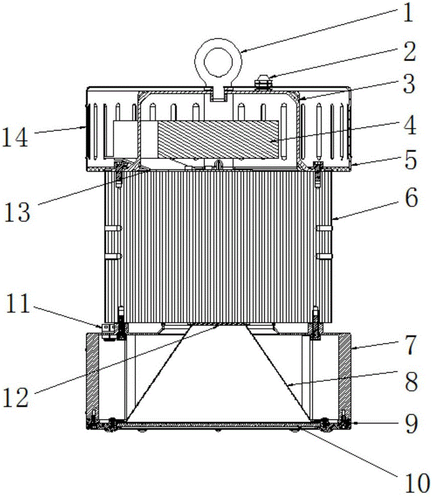
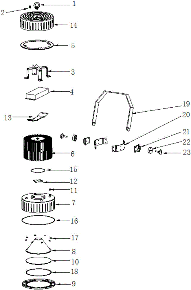
[0033] Such as figure 1 , figure 2 As shown, the shape of the entire high pole lamp is lantern-shaped, and the lamp body of the high pole lamp includes a hanging ring, a power supply cover assembly, a radiator assembly and a reflector assembly from top to bottom. The hanging ring 1 is arranged on the top of the lampshade assembly. The power supply cover assembly mainly includes a power supply cover 14 and a power supply 4 inside it. The top of the power supply cover 14 is provided with a waterproof power cord buckle 2, and the power supply cover shell fixing base 5 is pressed against the power supply cover 14 through the power supply cover shell fixing plate 3. The bottom of the power cover housing fixing plate 13 is fixedly connected with the top of the cooling assembly, and the power supply 4 is fixed inside the power supply cover through the power supply fixing seat 13. The radiator assembly mainly includes a radiator 6, which is respectively fixedly connected with the p...


PUM


Abstract

The invention provides an ultrahigh-power LED high-pole lamp which is mainly composed of a hanging ring, a power supply cover assembly, a cooling device assembly and a light reflection cup assembly. The heat dissipation device assembly comprises a heat dissipation device. A plurality of grooves of the tiny size are formed in the upper surface of the bottom of the heat dissipation device. The lower surface of the bottom of the heat dissipation device makes tight contact with an LED light source. By means of tiny-size gas-liquid composite phase change heat dissipation, the cooling effect of the LED light source is greatly improved. Long-strip-shaped radial heat dissipation holes are designed in a power supply outer cover and are beneficial to heat dissipation and air convection of the heat dissipation device, a passageway for hot gas flow to flow smoothly is provided, and therefore the optimal whole-lamp air convection and heat exchange effect is ensured. A breather valve is arranged on a light reflection cup shell, and therefore gas pressure is kept balanced, expansion gas is prevented from attacking weak links, the situation of cracks and deformation is prevented, and the service life of the shell is prolonged. A support type angle regulation device is adopted, and therefore the irradiation angle can be vertically regulated according to requirements of installation places and irradiation angles.

Description

technical field [0001] The invention relates to an ultra-high-power LED high-mast light, in particular to an ultra-high-power lantern-type LED high-mast light capable of improving heat dissipation. Background technique [0002] In city squares, stations, docks, freight yards, highways, stadiums and overpasses, etc., it is necessary to use high pole lights with strong lighting capabilities. The current high pole light generally refers to a new type of lighting device composed of a steel column light pole above 15 meters and a high-power combined light frame. Traditional high-mast lamps generally use high-pressure sodium lamps. In order to ensure the stable operation of the bulbs, ballasts must be connected in series in the circuit. At present, the ballasts used with high-pressure sodium lamps are inductive ballasts. Its disadvantage is that it is bulky, energy-consuming and expensive. At the same time, the lighting circuit of the high-pressure sodium lamp is a nonlinear ci...

Claims


Application Information

Patent Timeline
Patent Type & Authority Applications(China)
IPC IPC(8): F21S8/08F21V29/83F21V29/89F21V29/77F21V29/51F21V19/00F21V21/14F21V15/00F21Y101/02
CPCF21S8/085F21V15/00F21V19/001F21V21/14
Inventor 梁志刚李兵王念东陈军
Owner 湖南微酷光电科技有限公司
Why Eureka
Try Eureka