A kind of grinding jig and fixture thereof

A technology for grinding jigs and jigs, which is applied in the direction of grinding devices, grinding machine tools, manufacturing tools, etc., to achieve the effects of reducing force, extending length, and fast fixing speed

Active Publication Date: 2017-09-26
SUZHOU TFC OPTICAL COMM CO LTD
View PDF9 Cites 0 Cited by
  • Summary
  • Abstract
  • Description
  • Claims
  • Application Information

AI Technical Summary

Problems solved by technology

[0007] Therefore, the technical problem to be solved by the present invention is to overcome the technical defect that the grinding jig in the prior art cannot have the advantages of fast clamping speed and stable and accurate positioning at the same time, so as to provide a fast clamping speed and stable and accurate positioning. Grinding fixture

Method used


Image

  • A kind of grinding jig and fixture thereof
  • A kind of grinding jig and fixture thereof
  • A kind of grinding jig and fixture thereof

Examples


Embodiment 1

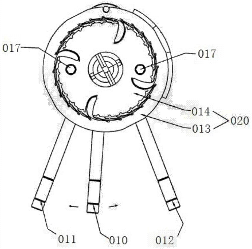
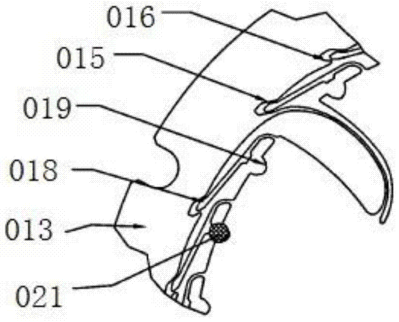
[0067] This embodiment provides a grinding fixture, such as Figure 4-5 As shown, it includes a disc-shaped clamp body 1; elastic positioning arms 2 have free ends and connecting ends, and the connecting ends of a plurality of elastic positioning arms 2 are uniformly fixed on the circumferential outer wall of the clamping body 1; the first extruding The surface 21 is arranged on the outer wall of one elastic positioning arm 2; the second extrusion surface 22, opposite to the first extrusion surface 21, is arranged on the inner wall of the other elastic positioning arm 2; the other elastic positioning arm 2 It is close to the one elastic positioning arm 2 under the action of its own elastic force, so that the first extrusion surface 21 and the second extrusion surface 22 are connected close to each other, so as to squeeze the first position of the positioning ferrule 3; and Under the action of external force, overcome its own elastic force and set a distance away from the elast...

Embodiment 2

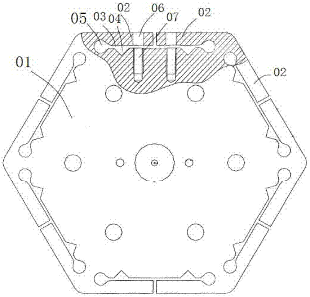
[0075] This embodiment provides a jig, which is used to cooperate with the jig in Embodiment 1, such as Figure 6-7 shown, including:

[0076] The base 5 includes a base 51, the base 51 has a bearing surface 52, a positioning plate 53 is fixed on the bearing surface 52, and a circular through hole 54 is provided on the positioning plate 53, and after the positioning plate 53 is fixed on the bearing surface 52, the circle A circular groove 50 is formed at the position of the shaped through hole 54;

[0077] The jig body 6 is rotatably installed inside the circular groove 50, the middle part is provided with an installation space 61 suitable for the installation of the grinding fixture, and the inner side is provided with a free end (insert part 25) suitable for the elastic positioning arm 2. ) cooperate with the jig groove 62 inserted, and the jig groove 62 corresponds to the free end of the elastic positioning arm 2 one by one;

[0078] Under the action of external force, th...


PUM


Abstract

The invention provides a grinding clamp and a jig thereof. When an insertion core needs to be located and fixed, only the free end of the jig needs to be pulled towards the side away from a clamp body to enable a first extrusion face to be separated from a second extrusion face by a certain distance; then the insertion core is put between the first extrusion face and the second extrusion face, an elastic locating arm is loosened and restores to the original position under the action of elasticity of the elastic locating arm, and accordingly the insertion core can be fixed between the first extrusion face and the second extrusion face rapidly and firmly, and the fixing speed is high. As the insertion core is fixed at a time, the process of gradual extrusion of a screw is avoided in the process of fixing, small displacement due to gradual extrusion can be prevented, and the insertion core does not move any more once being extruded and fixed, so that the locating is accurate; besides, the elasticity of the elastic locating arm is large, so that the insertion core is extruded and fixed quite firmly, and position changing or falling of the insertion core due to external slight impact is prevented.

Description

technical field [0001] The invention relates to the technical field of clamping tools, in particular to a grinding jig for clamping a ceramic ferrule and a jig thereof. Background technique [0002] The connection end face of the fiber optic ceramic ferrule needs to be ground to be as smooth as a mirror, so that the transmitted optical signal can pass through the connection smoothly without excessive photometric attenuation. In order to process the connection end faces of multiple optical fiber ceramic ferrules at the same time, it is necessary to fix the multiple ferrules to the grinding jig at the same time, and then place the grinding jig on the grinding machine for grinding. [0003] Chinese patent document CN201279708Y discloses a kind of optical fiber ceramic ferrule integral grinding disc, such as figure 1 As shown, it includes a grinding disc main body 01 and an elastic pressing arm 02. One end of the elastic pressing arm 02 is a free end, and the other end is fixed...

Claims


Application Information

Patent Timeline
Patent Type & Authority Patents(China)
IPC IPC(8): B24B37/27B24B37/34
CPCB24B37/27B24B37/34
Inventor 邹支农
Owner SUZHOU TFC OPTICAL COMM CO LTD
Why Eureka
Try Eureka