
Clamping mechanism for material shearing

A clamping mechanism and clamping member technology, applied in the direction of shearing devices, accessories of shearing machines, metal processing equipment, etc. cut etc.

Active Publication Date: 2015-12-09
江苏鼎旭节能建材科技有限公司
View PDF5 Cites 8 Cited by
  • Summary
  • Abstract
  • Description
  • Claims
  • Application Information

AI Technical Summary

Problems solved by technology

In the process of shearing, the clamping mechanism is required to clamp and fix the pipe, but most of the current clamping mechanisms are unidirectional clamping, such as only horizontal clamping, and at the same time, the clamping diameter of the pipe is also limited. It is necessary to manually clamp the clamped pipes, which is not conducive to quickly realize the shearing operation of a large number of pipes
[0003] On the other hand, in terms of the transmission of the clamping equipment, the equipment used is relatively large, which is not conducive to transportation and adjustment of the direction. The implementation site is somewhat limited, and the clamping and shearing on site cannot be performed, and its flexibility is limited.

Method used


Image

  • Clamping mechanism for material shearing
  • Clamping mechanism for material shearing
  • Clamping mechanism for material shearing

Examples


Embodiment Construction

[0040] The following description serves to disclose the present invention to enable those skilled in the art to carry out the present invention. The preferred embodiments described below are only examples, and those skilled in the art can devise other obvious variations.

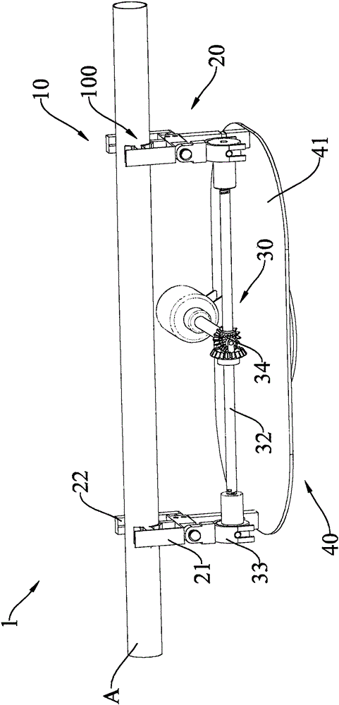
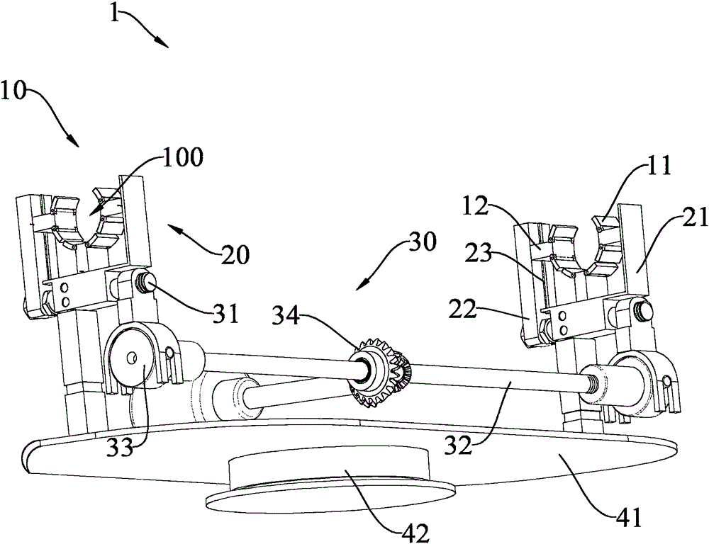
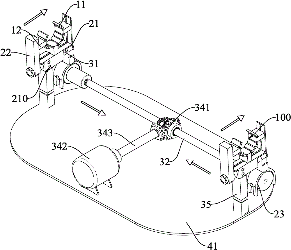
[0041] Such as Figure 1 to Figure 3 Described is a material shearing and clamping mechanism 1, the material shearing and clamping mechanism 1 includes a pair of clamping members 10, and the clamping members 10 are symmetrically arranged on the material shearing and clamping mechanism 1 Each clamping member 10 includes multiple pairs of clamping hands 11 and multiple clamping arms 12 that can be adjusted to connect the clamping hands 11, wherein the clamping hands 11 form a clamping cavity 100 , for placing the pipe A; a pair of support frames 20, each of the support frames 20 is operatively connected to each of the clamping arms 12, so as to support the clamping member 10, wherein each of the support frame...


PUM


Abstract

The invention provides a clamping mechanism for material shearing. The clamping mechanism for the material shearing comprises clamping assemblies, support frames and a driving device. The clamping assemblies are symmetrically arranged on the two sides of the a clamping mechanism body, and each clamping assembly comprises clamping hands and clamping arms which are connected with the clamping hands in an adjustable mode, wherein a clamping cavity is formed by each clamping hand and used for containing a pipe; all the support frames are connected with the clamping arms in an operable mode so as to support the clamping assemblies, wherein each support frame comprises a fixed arm and a free arm which can move relative to the fixed arm, so that the clamping assemblies can be kept in a relaxing state or in a clamping state; the driving device is connected with the support frames in a drivable mode, the driving device comprises longitudinal screw rods, transverse screw rods and a driving component, wherein the longitudinal screw rods are slidably hinged to the support frames to control the relative movement of the free arms, the transverse screw rods are connected to the longitudinal screw rods in a drivable mode so as to make the transverse movement of the support frames transformed into the longitudinal movement of the free arms, and the driving component is used for automatically driving the rotation of the transverse screw rods.

Description

technical field [0001] The invention relates to a mechanical clamping mechanism, specifically, a clamping mechanism suitable for cutting pipes in various ways. Background technique [0002] The use of pipe fittings is relatively extensive, ranging from small living and catering to large industrial buildings. There are strict standards for the use of different pipes, such as the diameter and length of the pipe. During the manufacturing process of the finished pipe, it is necessary to strictly control the diameter and length of the pipe, and cut the pipe according to the preset length value. Make a cut. In the process of shearing, the clamping mechanism is required to clamp and fix the pipe, but most of the current clamping mechanisms are unidirectional clamping, such as only horizontal clamping, and at the same time, the clamping diameter of the pipe is also limited. The clamped pipes need to be clamped manually, which is not conducive to quickly realizing the shearing oper...

Claims


Application Information

Patent Timeline
IPC IPC(8): B23D33/02
Inventor 冷建军张芳
Owner 江苏鼎旭节能建材科技有限公司
Learn More