Directly-operated automatic water replenishing valve for solar water heater

A technology for solar water heaters and automatic water replenishment, applied to valve details, valve devices, engine components, etc., can solve the problems of poor appearance and reliability, complicated installation, high cost, etc., and achieve the effect of compact structure, convenient installation and transportation, and low cost

Active Publication Date: 2015-12-09
YUXI XINGHONG SOLAR ENERGY EQUIP +1
View PDF6 Cites 1 Cited by
  • Summary
  • Abstract
  • Description
  • Claims
  • Application Information

AI Technical Summary

Problems solved by technology

Poor appearance and reliability, complicated installation and high cost

Method used


Image

  • Directly-operated automatic water replenishing valve for solar water heater
  • Directly-operated automatic water replenishing valve for solar water heater
  • Directly-operated automatic water replenishing valve for solar water heater

Examples


Embodiment 1

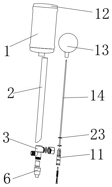
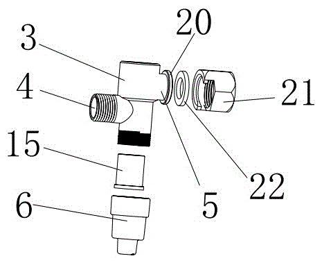
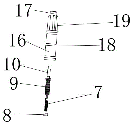
[0021] Such as figure 1 As shown, the direct-acting automatic replenishment valve for solar water heaters includes a floating bucket 1, a water level pipe 2 and a valve body 3; The wall is provided with an inlet pipe 4 and an outlet pipe 5. The inlet pipe 4 and the outlet pipe 5 are located on opposite sides of the valve body and are staggered up and down. The inlet pipe 4 is located below the outlet pipe 5; There is a round hole at the bottom of the sleeve 6, a screw rod 7 is installed in the round hole, an adjusting nut 8 is installed outside the screw rod 7 through the round hole, a cylindrical spring 9 is arranged above the screw rod 7, a screw 10 is arranged on the top of the cylindrical spring 9, and a valve is installed above the screw 10 The core 11, the side wall of the valve core 11 matches the shape of the inner cavity of the valve body 3; the water level pipe 2 is installed above the valve body 3, and the floating water bucket 1 is installed above the water level p...

Embodiment 2

[0024] Such as figure 1 As shown, the direct-acting automatic replenishment valve for solar water heaters includes a floating bucket 1, a water level pipe 2 and a valve body 3; The wall is provided with an inlet pipe 4 and an outlet pipe 5. The inlet pipe 4 and the outlet pipe 5 are located on opposite sides of the valve body and are staggered up and down. The inlet pipe 4 is located below the outlet pipe 5; The water pipe 5 is kept in communication with the water level pipe at any time, so that the water level pipe is consistent with the water level of the incubator, and the existing axial water inlet is changed to realize radial water inlet. The axial force of the valve core is independent of the water inlet pressure. The spool moves vertically and axially.

[0025] A fixed sleeve 6 is installed below the valve body 3, and there is a circular hole at the bottom of the fixed sleeve 6. A screw rod 7 is installed in the circular hole, and an adjusting nut is installed outside ...


PUM


Abstract

The invention relates to the technical field of water replenishing for floating ball valves for domestic solar water heaters, particularly relates to a directly-operated automatic water replenishing valve for a solar water heater, and solves the problem of water replenishing for solar insulation boxes. The directly-operated automatic water replenishing valve for the solar water heater comprises a floating water bucket, a water level tube and a valve body, wherein the valve body is a four-way valve body; the valve body axially and vertically penetrates through an opening; a water inlet tube and a water outlet tube are arranged on the sidewall of the valve body; the water inlet tube and the water outlet tube are located at the two opposite sides of the valve body, and vertically and mutually staggered; the water level tube is installed above the valve body; the floating water bucket is installed above the water level tube; a floating ball is arranged in the floating water bucket; a floating rod is arranged below the floating ball; and the floating rod penetrates through the water level tube and stretches into the valve body to be connected together with a valve element. The automatic water replenishing valve is small in size and integrates the floating ball.

Description

technical field [0001] The invention relates to the technical field of water replenishment by a float valve of a household solar water heater, in particular to a direct-acting automatic water replenishment valve for a solar water heater. Background technique [0002] People need water storage equipment in life and production, including thermal insulation water tanks for solar water heaters, water tanks for central heating systems, water towers for industrial and mining enterprises, fire pools and boiler water tanks, etc. Automatic liquid level control devices are used in these equipment Performing rehydration saves labor and prevents water wastage. When tap water is used to replenish water to the above-mentioned water storage equipment, it is convenient and economical to apply a water level control valve to replenish water. But the existing water level control valve is a kind of ball float valve, and the ball float and the connecting rod are outside the valve body, so there...

Claims


Application Information

Patent Timeline
Patent Type & Authority Applications(China)
IPC IPC(8): F16K31/22
CPCF16K31/22
Inventor 雷兴红雷飞王蕊
Owner YUXI XINGHONG SOLAR ENERGY EQUIP
Why Eureka
Try Eureka