Feed supply device controlled to ascend and descend through air pressure

A technology of air pressure control and supply device, which is applied in the direction of animal feeding device, application, poultry industry, etc., and can solve problems such as difficult to lock, difficult to achieve supply effect, waste of feed, etc.

Inactive Publication Date: 2015-12-16
俞升洋
View PDF7 Cites 2 Cited by
  • Summary
  • Abstract
  • Description
  • Claims
  • Application Information

AI Technical Summary

Problems solved by technology

[0004] However, some existing related devices are either fixed in structure, which is not convenient for unified maintenance and operation, o...

Method used


Image

  • Feed supply device controlled to ascend and descend through air pressure
  • Feed supply device controlled to ascend and descend through air pressure
  • Feed supply device controlled to ascend and descend through air pressure

Examples


Embodiment Construction

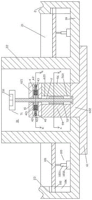
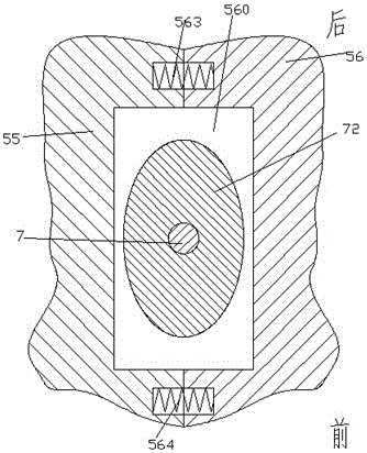
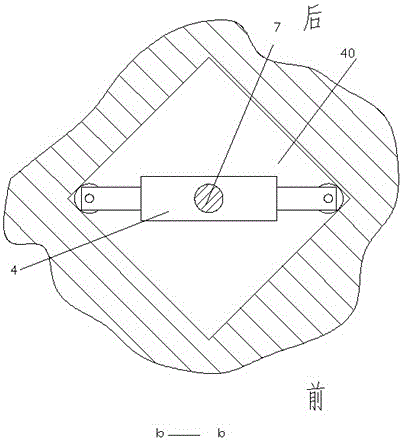
[0011] Combine below Figure 1-3 The present invention will be described in detail.

[0012] According to an embodiment, a feed supply device controlled by air pressure lifts, comprising a bearing chassis 61 and a vertically fixed column part 62 fixedly connected to the bearing chassis 61, the fixed body part 62 includes a horizontally extending The telescopic through hole 620 of the slider, the top wall part 621 located on the upper side of the telescopic through hole 620 of the slider, and the column root part 622 located on the lower side of the telescopic through hole 620 of the slider and directly connected with the carrying chassis , two locking sliders 55, 56 symmetrical to the axis of the solid cylinder part 62 are slidably arranged in the slider telescopic through hole 620, and the two locking sliders 55, 56 can move toward each other and retract into the telescopic through hole 620 of the slider and lean against each other. At this time, the inner sides of the two l...


PUM


Abstract

A feed supply device controlled to ascend and descend through air pressure comprises a fixing column part (62) provided with a bearing bottom plate (61) and fixedly connected with the bearing bottom plate (61) in the vertical direction. The fixing column part (62) comprises a slider telescopic through hole (620) extending in the horizontal direction, a top wall part (621) located on the upper side of the slider telescopic through hole (620), a column root part (621) located on the lower side of the slider telescopic through hole (620) and directly and fixedly connected with the bearing bottom plate. Two locking sliders (55 and 56) symmetric about the axis of the fixing column part (62) are arranged in the slider telescopic through hole (620) in a sliding mode.

Description

technical field [0001] The invention relates to the field of feed, in particular to a feed supply device whose lifting is controlled by air pressure. Background technique [0002] In some current farming fields, large-scale industrialization is often adopted to improve production efficiency and reduce costs. [0003] For the feed delivery device or supply device, in order to adapt to large-scale industrial production, it needs to be convenient for unified maintenance, such as cleaning and disinfection or disassembly and installation, and it is required to have a stable position after installation and not be easily disturbed during use. . [0004] However, some existing related devices are either fixed in structure, which is not convenient for unified maintenance and operation, or has a weak structure or is difficult to lock, which causes feed waste or is difficult to achieve the shortcoming of supplying effect during use. Contents of the invention [0005] The object of ...

Claims


Application Information

Patent Timeline
IPC IPC(8): A01K5/02A01K39/012
CPCA01K5/0225A01K39/0125
Inventor 俞升洋
Owner 俞升洋
Why Eureka
Try Eureka