LED display drive control method and device, LED light board

A technology of LED light panels and LED lights, which can be applied to static indicators, instruments, etc., can solve problems such as the first scan being too dark, and achieve the effect of reducing afterglow

Active Publication Date: 2018-01-12
XIAN NOVASTAR TECH
View PDF7 Cites 0 Cited by
  • Summary
  • Abstract
  • Description
  • Claims
  • Application Information

AI Technical Summary

Problems solved by technology

[0007] From the above analysis, it can be seen that in the LED screen using a general-purpose on-off driver chip or a PWM driver chip, the existing scanning method with a fixed sequence will lead to low gray due to the influence of the column line parasitic capacitance. The problem with the first sweep of the dark

Method used


Image

  • LED display drive control method and device, LED light board
  • LED display drive control method and device, LED light board
  • LED display drive control method and device, LED light board

Examples


Embodiment Construction

[0026] In order to make the above objects, features and advantages of the present invention more comprehensible, specific implementations of the present invention will be described in detail below in conjunction with the accompanying drawings.

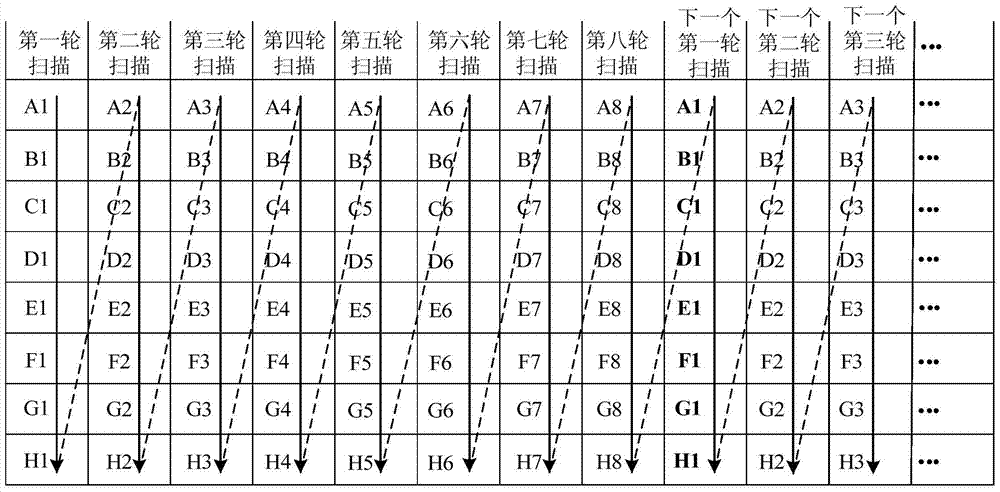
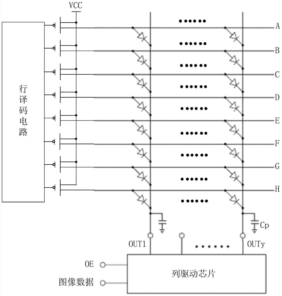
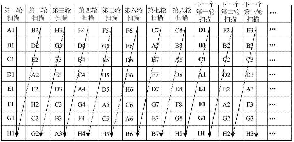
[0027] See image 3 , a LED display driving control method proposed by the embodiment of the present invention can be applied to figure 2 The LED light board shown.

[0028] Such as figure 2 As shown, the LED light board includes: a plurality of scanning lines A~H, a plurality of data lines, a plurality of LED lamps electrically connected to the plurality of scanning lines A~H and the plurality of data lines, a row decoding circuit and A column drive chip; wherein, the multiple scan lines A to H are electrically connected to the row decoding circuit through a row selection switch such as a PMOS transistor, and the multiple data lines are respectively electrically connected to each output terminal OUT1 of the column drive chip, ......


PUM


Abstract

The invention relates to an LED display driving control method, which is used to drive and control a plurality of LED lamps electrically connected to M scanning lines, wherein M is a positive integer greater than 1; the LED display driving control method includes the steps of: sequentially performing N Each round scans M scans, where N is a positive integer greater than 1. Furthermore, the scanning lines corresponding to the first scan in the M scans performed by each of the N rounds of scanning are different. The invention also provides an LED lamp panel adopting the method and an LED display driving control device realizing the method. The present invention changes the position of the first sweep in at least some of the multiple rounds of scanning in the prior art, for example, each round of scanning uses a random scanning sequence, so that each scanning line may become the first sweep, thereby solving the problem of LED The low gray scale of the display is dim first scan, and by using a random scan order, afterglow and "caterpillar" issues can be mitigated.

Description

technical field [0001] The invention belongs to the technical field of LED display control, and in particular relates to an LED display drive control method, an LED lamp panel and an LED display drive control device. Background technique [0002] Since 2012, the pitch of LED display screens has broken through below P3, but in the process of use, the dimming of the first scan has always been a bottleneck for high-density small-pitch LED displays. [0003] At present, when the LED scanning display control system drives the LED screen with a general-purpose on-off driver chip, the gray scale is realized through subfields. Turn on the time to realize the weight corresponding to the bit. Usually, in order to improve the refresh rate of the scanning display screen, it is not to achieve the gray level of a certain line before realizing the gray level of the next line, but to divide the total number of sub-fields required to achieve the full gray level into multiple parts, for exam...

Claims


Application Information

Patent Timeline
Patent Type & Authority Patents(China)
IPC IPC(8): G09G3/32
Inventor 梁伟刘德福王伙荣
Owner XIAN NOVASTAR TECH
Why Eureka
Try Eureka