Light emitting diode drive device and illumination device

a technology of light-emitting diodes and drive devices, which is applied in the direction of semiconductor devices for light sources, electroluminescent light sources, lighting and heating apparatus, etc., can solve the problem of insufficient red color reproducibility

Inactive Publication Date: 2018-10-16
SHARP KK
View PDF30 Cites 0 Cited by
  • Summary
  • Abstract
  • Description
  • Claims
  • Application Information

AI Technical Summary

Benefits of technology

[0022]According to the aspect of the present invention, it is possible to obtain a light emitting diode drive device which reduces an afterglow of secondary light, and an illumination device.

Problems solved by technology

However, in a case where the CASN phosphor which is a phosphor disclosed in PTL 1 is used, a wavelength width of the emission spectrum of the red phosphor is equal to or greater than 80 nm, and thus, the color reproducibility of red is not sufficient.

Method used


Image

  • Light emitting diode drive device and illumination device
  • Light emitting diode drive device and illumination device
  • Light emitting diode drive device and illumination device

Examples


embodiment 1

[0043]Hereinafter, Embodiment 1 according to the present disclosure will be described in detail.

[0044](Configuration of Illumination Device 1)

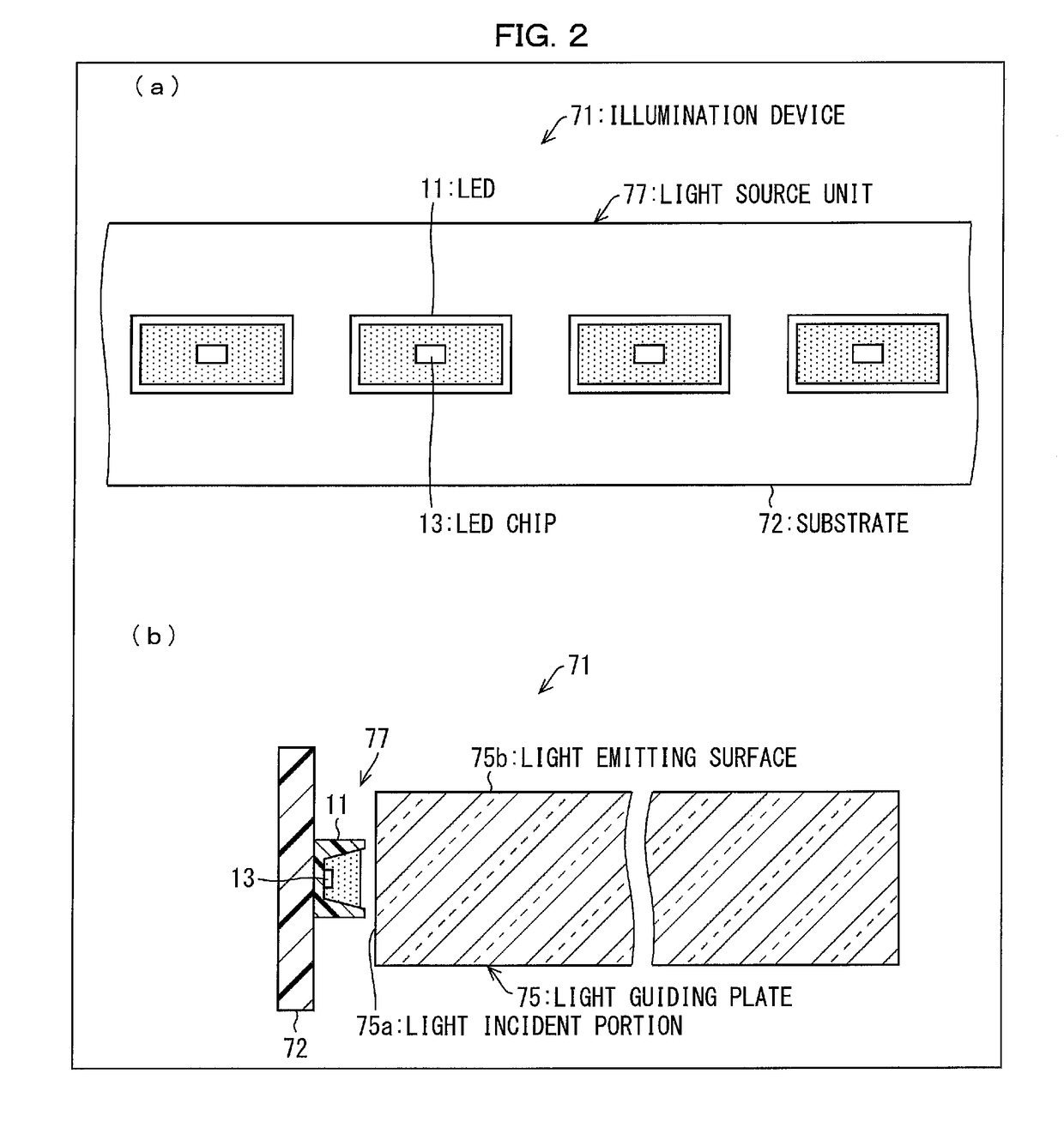
[0045]In the beginning, an illumination device 71 which uses an LED (light emitting diode) 11 according to the present embodiment will be described. FIG. 2(a) is an expanded plan view illustrating a part of the illumination device 71 which uses the LED 11 according to Embodiment 1, and FIG. 2(b) is a sectional view of the illumination device 71 illustrated in FIG. 2(a).

[0046]As illustrated in FIGS. 2(a) and 2(b), the illumination device 71 includes a substrate 72, multiple LEDs 11 and a light guiding plate 75. The illumination device 71 also includes an LED drive control unit (refer to FIG. 1), which is not illustrated in FIG. 2, for controlling driving of the multiple LEDs 11.

[0047]The entire light guiding plate 75 has a rectangular shape, and is a transparent member having a predetermined thickness. The light guiding plate 75 has a structure...

embodiment 2

[0158]Embodiment 2 according to the present invention will be hereinafter described with reference to FIG. 12 and FIG. 20. For the sake of convenience of description, the same symbols or reference numerals will be attached to the members having the same functions as described in Embodiment 1, and description thereof will be omitted.

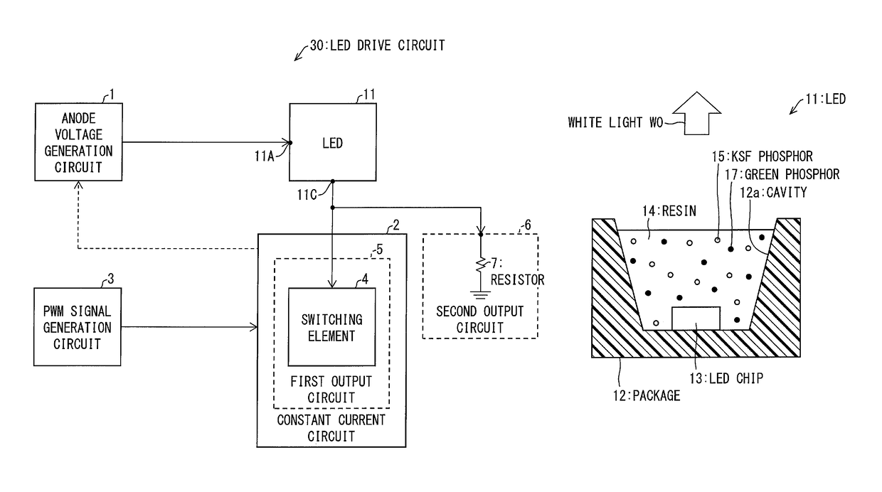
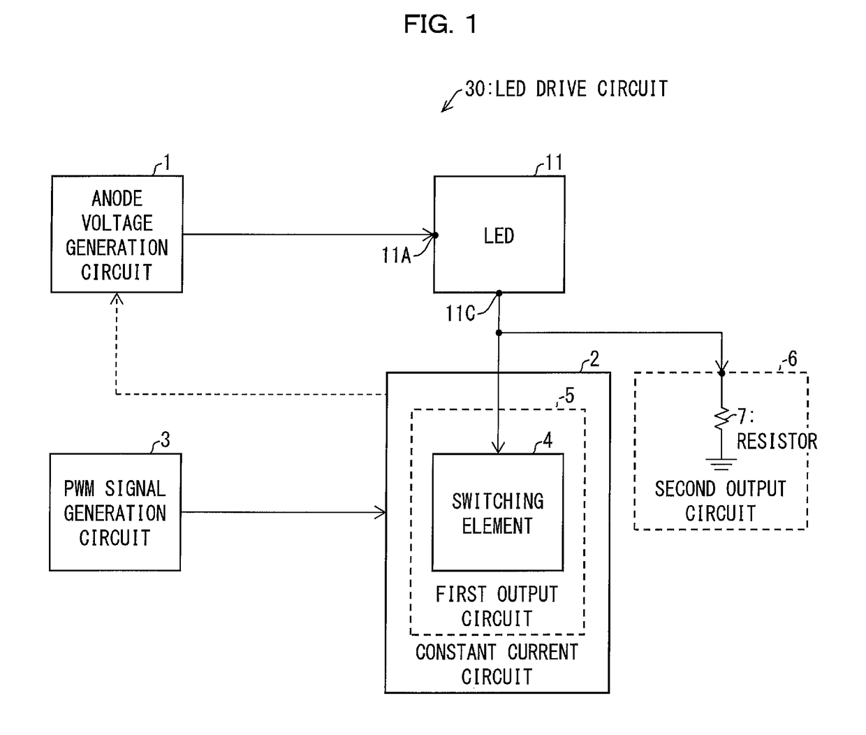
[0159]FIG. 12 is a block diagram illustrating a configuration of an LED drive circuit (light emitting diode drive device) 31 according to Embodiment 2. The LED drive circuit 31 is different from the LED drive circuit 30 in that a second output circuit 61 and a PWM signal generation circuit 3A are included instead of the second output circuit 6. The other configurations of the LED drive circuit 31 are the same as the LED drive circuit 30.

[0160]The second output circuit 61 includes a switching element 41 in addition to the resistor 7. The cathode 11C of the LED 11 is coupled to the switching element 4 which is the first output circuit 5, and is also coupled...

embodiment 3

[0173]Embodiment 3 of the present invention will be hereinafter described with reference to FIG. 13. For the sake of convenience of description, the same symbols or reference numerals will be attached to the members having the same functions as described in Embodiment 1 and Embodiment 2, and description thereof will be omitted.

[0174]FIG. 13 is a block diagram illustrating a configuration of an LED drive circuit (light emitting diode drive device) 32 according to Embodiment 3. The LED drive circuit 32 is different from the LED drive circuit 30 in that a current control circuit 21 and a first output circuit 51 are included instead of the constant current circuit 2. The other configurations of the LED drive circuit 32 are the same as the LED drive circuit 30. The LED drive circuit 32 is different from the LED drive circuit 30 in that the first output circuit 51 is disposed in the outside of the current control circuit 21. The first output circuit 51 includes a switching element 42 and ...


PUM


Abstract

To provide a circuit for reducing an afterglow of secondary light, a circuit includes an LED (11) which includes an LED chip (13) and a KSF phosphor (15), and a first output circuit (5) and a second output circuit (6) which are coupled to a cathode (11C). When a PWM signal goes to “H”, the first output circuit is driven thereby making IF flow from the cathode. When the PWM signal goes to “L”, the first output circuit stops driving, and the second output circuit makes an offset current flow from the cathode.

Description

TECHNICAL FIELD[0001]The present invention relates to a light emitting diode drive device and an illumination device.BACKGROUND ART[0002]For a backlight which is used for a so-called liquid crystal television (TV), an LED chip which emits blue light as primary light, a red phosphor which is excited by the blue light and emits red light as secondary light, and a green phosphor which emits green light are used. The backlight is emitted as white light which is obtained by mixing blue light, green light, and red light.[0003]PTL 1 discloses a light emitting element which emits white light by exciting divalent Eu-activated CaAlSiN3 (hereinafter, referred to as CASN phosphor) that is a nitride-based phosphor for emitting red light, and a green phosphor that emits green light, using an LED for emitting blue light.[0004]In addition, an Eu-activated β type SiAlON phosphor which is disclosed in, for example, PTL 2 has been appropriately used in the related art, as a phosphor which emits green ...

Claims


Application Information

Patent Timeline
Patent Type & Authority Patents(United States)
IPC IPC(8): F21V7/22H05B33/08F21Y115/10H05B44/00H05B45/50H05B45/59
CPCH05B33/0815F21V7/22H05B33/086H05B33/0845H05B33/0887H05B33/0818F21Y2115/10H05B45/305H05B45/10H05B45/50H05B45/325H05B47/10H05B45/345H05B45/59Y02B20/40
Inventor YAMASHITA, ATSUSHIONOZAKI, MANABUONO, TSUYOSHIMIYATA, MASATAKA
Owner SHARP KK
Why Eureka
Try Eureka