Visual interface modeling editor for building interface model

An interface model and editor technology, applied in the direction of program control devices, etc., can solve the problems of loss of diversity and flexibility of interface development, complex and confusing views, etc., to achieve convenient top-down analysis and design, and modeling granularity control, convenient integration and integrated effects

Active Publication Date: 2016-01-27
CHENGDU PUZHONG SOFTWARE CO LTD
View PDF5 Cites 7 Cited by
  • Summary
  • Abstract
  • Description
  • Claims
  • Application Information

AI Technical Summary

Problems solved by technology

However, this type of graphical interface assembly method based on prefabricated components still has two major disadvantages: first, it does not allow user-defined components, and does not provide operating rules for user-defined components, thus limiting the possibility of expression and user extension Therefore, the diversity and flexibility required for interface development will be lost, especially the interface development that cannot adapt to large and complex systems; second, when the interface functions become complex, the view assembled with prefab primitives becomes extremely complicated and confusion, especially the intersecting data lines make the interface view unreadable. Therefore, this kind of software is usually only used for simple interface development, and cannot meet the needs of large-scale and complex interface development;
[0005] In general, there is still a lack of a universal, easy-to-use, and standardized visual interface modeling software that can be easily understood and mastered by ordinary people in the field, and supports the construction of complex interface systems in various fields. Modeling activities to construct interface views that can be automatically converted into computer-runable codes using object-oriented techniques

Method used


Image

  • Visual interface modeling editor for building interface model
  • Visual interface modeling editor for building interface model
  • Visual interface modeling editor for building interface model

Examples


Embodiment

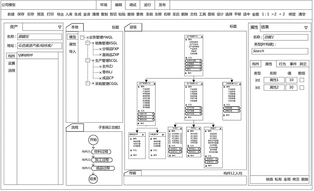
[0095] Embodiment: business management YWGL interface editing

[0096] The business model of the enterprise assumed in this embodiment is to obtain profits by selling products produced by itself and products purchased externally, and the business management interface that realizes the following business management intentions will be modeled:

[0097] (1) Clearly distinguish the three interface modules of production management, purchase management and sales management;

[0098] (2) Configuration function: Configure the number of self-produced products and the number of externally purchased products through the interface, and configure the number of sales products by summing the number of produced products and the number of purchased products through the interface logic;

[0099] (3) Operation display function: the sales management interface implements the input of the contract order quantity and shipment quantity for the distribution and direct sales of each product; the produc...


PUM


Abstract

The invention discloses a visual interface modeling editor for building interface models. The visual interface modeling editor uses an interface hierarchy editor, an interface port editor, an interface display editor, an interface algorithm editor, an interface flow editor, an interface transmission editor to complete construction of interface models and interface views respectively using an interface hierarchy model, an interface port model, an interface display model, an interface algorithm model, an interface flow model, an interface transmission model, and corresponding views as edit objects. The method provides a visual interface modeling tool for various fields, and the tool is advantaged by operation property, universality, and usability. The interface models and interface views structured by the method are clear in structures, adjustable in hierarchy, and controllable in modeling granularity, and have sufficient consistency of being operated. The method is uniform, and provides convenience for top-down analysis, and provides convenience for bottom-up integration, and the method is suitable to be used for various interface modeling. The modeling method is simple. The visual interface modeling editor can completely model in a visual manner. Even a person in an ordinary field can easily and independently structure an interface model and an interface view.

Description

technical field [0001] The invention relates to the technical field of interface engineering, in particular to a method for constructing an interface model based on an interface element model and a computer program product. Background technique [0002] The interface determines the success of a software to a large extent. The key reasons are: first, the interface is the concrete embodiment of the business, and second, the interface directly determines the user experience. At the same time, the software interface shows three characteristics: (1) diversity: the software is used in various fields, and the development theme of the software interface covers almost all application fields; The requirements of the interface in a project are also constantly changing; (3) Complexity: interface development occupies a considerable proportion of workload in software development. Because of the prominent position of the interface, the software tool for developing the interface is also ca...

Claims


Application Information

Patent Timeline
Patent Type & Authority Applications(China)
IPC IPC(8): G06F9/44
CPCG06F9/44
Inventor 符长明龙春生唐鸿
Owner CHENGDU PUZHONG SOFTWARE CO LTD
Why Eureka
Try Eureka