A specimen pressurizing device for three-dimensional photoelastic stress experiment

A pressurizing device and photoelastic technology, applied in the field of specimen pressurizing devices, can solve the problems of inconvenient movement, the inability of the pressurizing device to display the magnitude of the loading force, and the inability of the oven to bear the weight of excessive weights, so as to prolong the service life, The effect of large load value and accurate digital display of load value

Active Publication Date: 2018-05-11
WUHAN UNIV OF SCI & TECH
View PDF6 Cites 0 Cited by
  • Summary
  • Abstract
  • Description
  • Claims
  • Application Information

AI Technical Summary

Problems solved by technology

[0005] 1. Generally, the load is applied by adding weights. The gravity of the weights is completely applied to the bottom of the oven. The oven cannot bear the weight of the heavy weights, which limits the increase of the load value and cannot achieve high stress loading.
[0006] 2. Pressure devices using other loading methods cannot display the magnitude of the loading force
[0007] 3. When carrying out stress freezing, it is necessary to put the entire pressurizing device into the oven, which is inconvenient to move

Method used


Image

  • A specimen pressurizing device for three-dimensional photoelastic stress experiment
  • A specimen pressurizing device for three-dimensional photoelastic stress experiment
  • A specimen pressurizing device for three-dimensional photoelastic stress experiment

Examples


Embodiment 1

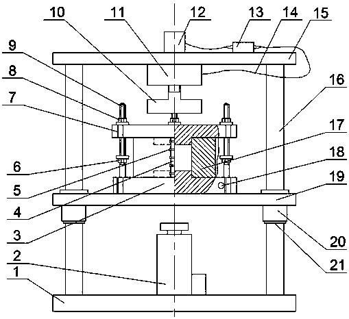
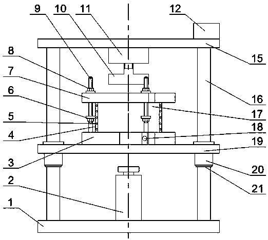
[0028] A specimen pressurizing device for three-dimensional photoelastic stress experiment. Such as figure 1 with figure 2 As shown, the specimen pressurization device for three-dimensional photoelastic stress experiment consists of three parts: loading device, pressure holding device and pressure measuring device.

[0029] Such as figure 1 with figure 2 As shown, the structure of the loading device is: a jack 2 is fixed at the middle position of the bottom plate 1, guide rods 16 are symmetrically fixed at four corners of the bottom plate 1, and ring-shaped bosses 21 are provided on the four guide rods 16 at equal heights; The four corners of 19 are fixed with sliding sleeves 20, and the four sliding sleeves 20 are looped on the corresponding guide rods 16. The sliding plate 19 is located on the annular boss 21. The height of the lower plane of the sliding plate 19 is 1.05 of the height of the initial position of the jack 2. ~1.10 times, the upper ends of the four guide ...

Embodiment 2

[0037] A specimen pressurizing device for three-dimensional photoelastic stress experiment. Except following technical parameter, all the other are with embodiment 1:

[0038] The height of the lower plane of the slide plate 19 is 1.10 to 1.15 times the height at the initial position of the jack 2;

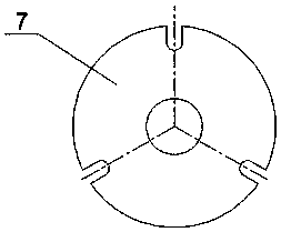
[0039] The die 17 is composed of two identical semi-cylinders, the outer walls of the four sides of the two semi-cylinders are respectively provided with ear plates 4, and the four sides are parallel to the axis of the semi-cylinders, and each ear plate 4 is symmetrically Screw holes are provided, and there are 4 screw holes. The bolt 5 connects the two half cylinders as a whole through the screw holes, and the wall thickness of the half cylinders is 35-50 mm.

[0040] Compared with the prior art, this specific embodiment has the following positive effects:

[0041] In this specific embodiment, the radial constraint is provided to the test piece through the die 17 , and the axia...


PUM

PropertyMeasurementUnit
thicknessaaaaaaaaaa
thicknessaaaaaaaaaa
thicknessaaaaaaaaaa

Abstract

The invention relates to a test piece pressurizing device for three-dimensional photoelastic stress experiment. The technical solution is: a jack (2) is fixed at the middle position of the bottom plate (1). The lower ends of the three clamping screws (9) are correspondingly hinged with the pins (18) arranged in the three U-shaped notches of the lower splint (3), and the upper ends of the three clamping screws (9) are correspondingly mounted on the upper splint (7) In the three U-shaped gaps, the upper parts of the three clamping screws (9) are respectively provided with the lower lock nut (6) and the upper lock nut (8), the circular boss of the lower splint (3) and the upper splint The circular boss of (7) is packed into the bottom and the top of die (17) correspondingly. The pressure measuring device is composed of a pressure sensor (11), a pressure head (10), a signal amplifier (13), a digital display meter (12) and a signal cable (14). The invention has the characteristics of large load value, accurate digital display of the load value, convenient removal of the test piece and constant load, and is suitable for three-dimensional photoelastic stress experimental research.

Description

technical field [0001] The invention belongs to the technical field of test piece pressurizing devices for photoelastic stress experiments. In particular, it relates to a specimen pressurizing device for three-dimensional photoelastic stress experiment. Background technique [0002] Photoelasticity method is an experimental stress analysis method that uses optical principles to study elastic mechanics problems. Put the structural specimen made of transparent material with birefringence effect in the polarized light field, when the load is applied to the specimen, the interference fringe pattern generated on the specimen can be seen. Through the interference fringes, the stress distribution at any point on the surface of the test piece and inside the test piece can be accurately calculated, so it is especially suitable for stress analysis of objects with complex geometric shapes and structures. [0003] In actual work, some structures are in a two-dimensional stress state, ...

Claims


Application Information

Patent Timeline
Patent Type & Authority Patents(China)
IPC IPC(8): G01N3/02
Inventor 叶义成胡南燕涂福泉王琦琳胡洪旺赵祖炜岳哲姚囝
Owner WUHAN UNIV OF SCI & TECH
Why Eureka
Try Eureka