Single-man manual-control rotorcraft

A gyrocopter and manual control technology, which is applied in the field of aircraft, can solve the problems of troublesome maintenance, difficult adaptation, and large production cost.

Inactive Publication Date: 2016-02-10
王略
View PDF5 Cites 11 Cited by
  • Summary
  • Abstract
  • Description
  • Claims
  • Application Information

AI Technical Summary

Problems solved by technology

[0004] However, at the beginning of the invention of the rotorcraft, its control mechanism was based on its driving characteristics, combined with the basis of the control structure of the fixed-wing aircraft. The main control method has been used until now without much change. Accelerator, the two feet are used to control the direction by pedaling. This driving method allows most fixed-wing aircraft pilots and helicopter pilots who also use similar operation methods to accept it almost without obstacles, but it is a problem for ordinary people. It is difficult to adapt to the process. In addition, the control of the driver's left and right hands and feet is independent. In each control mechanism controlled by the left and right hands and feet, there is a certain distance between the hands and feet and the actual control parts. A relatively independent and complicated set of control components is required to realize such a control mechanism. For the driver of the rotorcraft, maintenance and inspection are troublesome, but for the manufacturer, several sets of relatively independent and complicated controls Components will add greater production costs
[0005] Because the power of the rotorcraft comes from the engine propulsion or pull-in propeller, the diameter of the propeller is usually much larger than that of the fixed-wing aircraft of the same weight class. When the propeller is in the working state, the propeller surface acts on the air to generate power. The air also gives the propeller the same reaction force. After the reaction force is transmitted to the fuselage through the propulsion or pull-in propeller shaft, it will make the fuselage center on the propulsion or pull-in propeller shaft to produce a transverse direction opposite to the propeller rotation direction. Tilting and rolling, although the support wheels and columns on both sides are affected by this force during take-off and roll, the reaction force is concentrated on the support wheel on the opposite side of the propeller rotation direction during take-off, and Overcome by ground support, once the side support wheels of the fuselage leave the ground, the fuselage is in an unsupported state. At this time, the reaction force of the propeller will cause the fuselage to roll slightly immediately after the support wheels leave the ground. Experienced drivers Beginners can adjust the tilt angle of the rotor head in advance to balance through repeated practice, but beginners are often in a hurry because of this, causing the rotor to be destroyed due to excessive roll and touch the ground during take-off, and even cause the fuselage and the driver

Method used


Image

  • Single-man manual-control rotorcraft
  • Single-man manual-control rotorcraft
  • Single-man manual-control rotorcraft

Examples


Embodiment 1

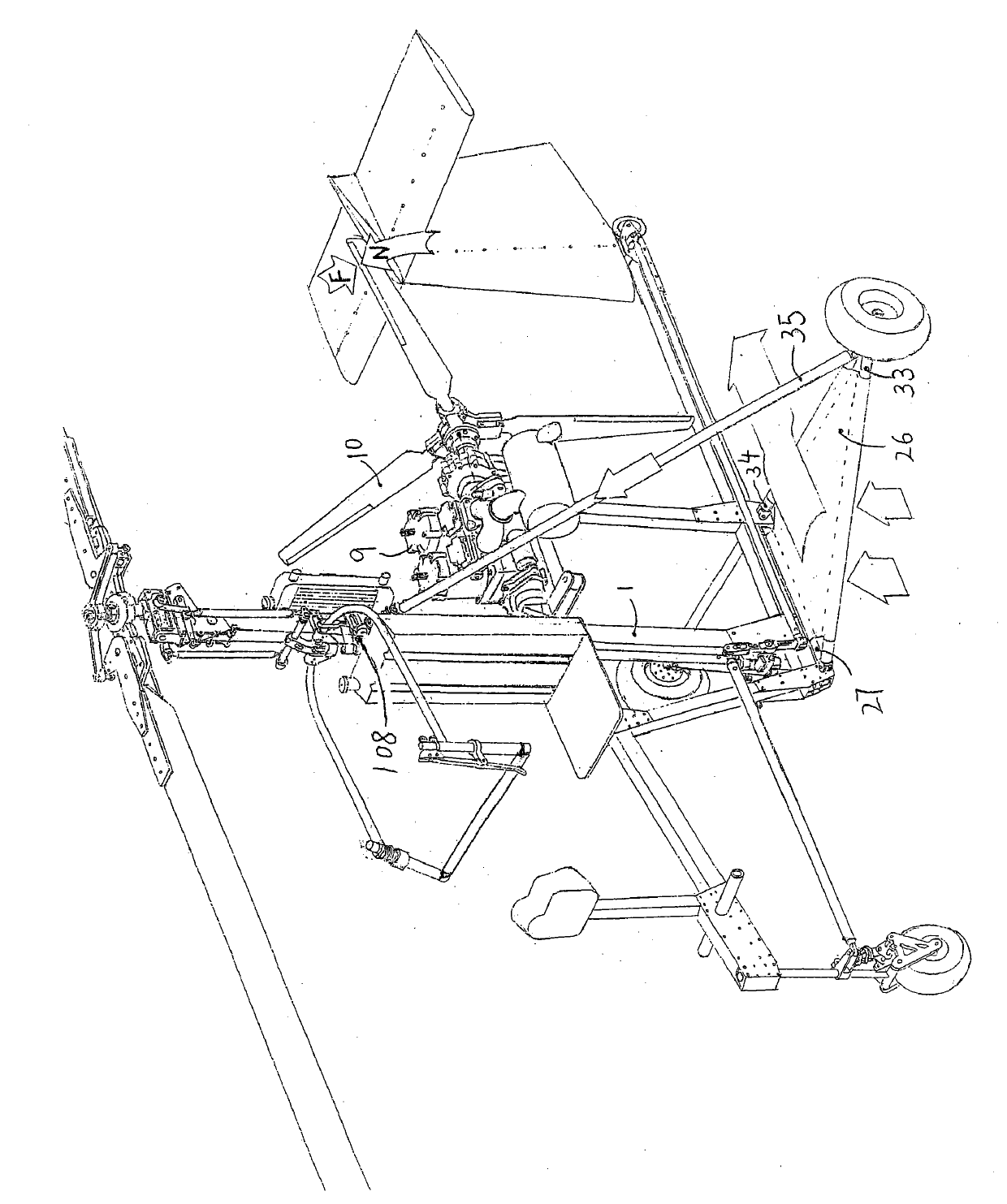
[0140] Embodiment one: if figure 1 , figure 2 As shown, the single-person manual rotorcraft of the present invention is composed of a fuselage part, a rotor shaft cantilever tilting structure, a full manual control mechanism, and an internal variable-distance rotor head mechanism. The wheel is directly in front, the tail is placed at the rear, the driver's seat and the engine are respectively placed at the front and rear of the column, the propeller is used as the power, and the three-point frame type independent shock-absorbing support mechanism with the propeller reaction force balance device is used to balance the air force when the propeller is working. The reaction force generated by the fuselage increases the stability of the whole machine itself. Through the full manual control mechanism with steering connection function, the driver can complete the rotor pitch change, rotor shaft tilt, Full manual operation of flight steering and brakes.

[0141] Such as figure 2 ...

Embodiment 2

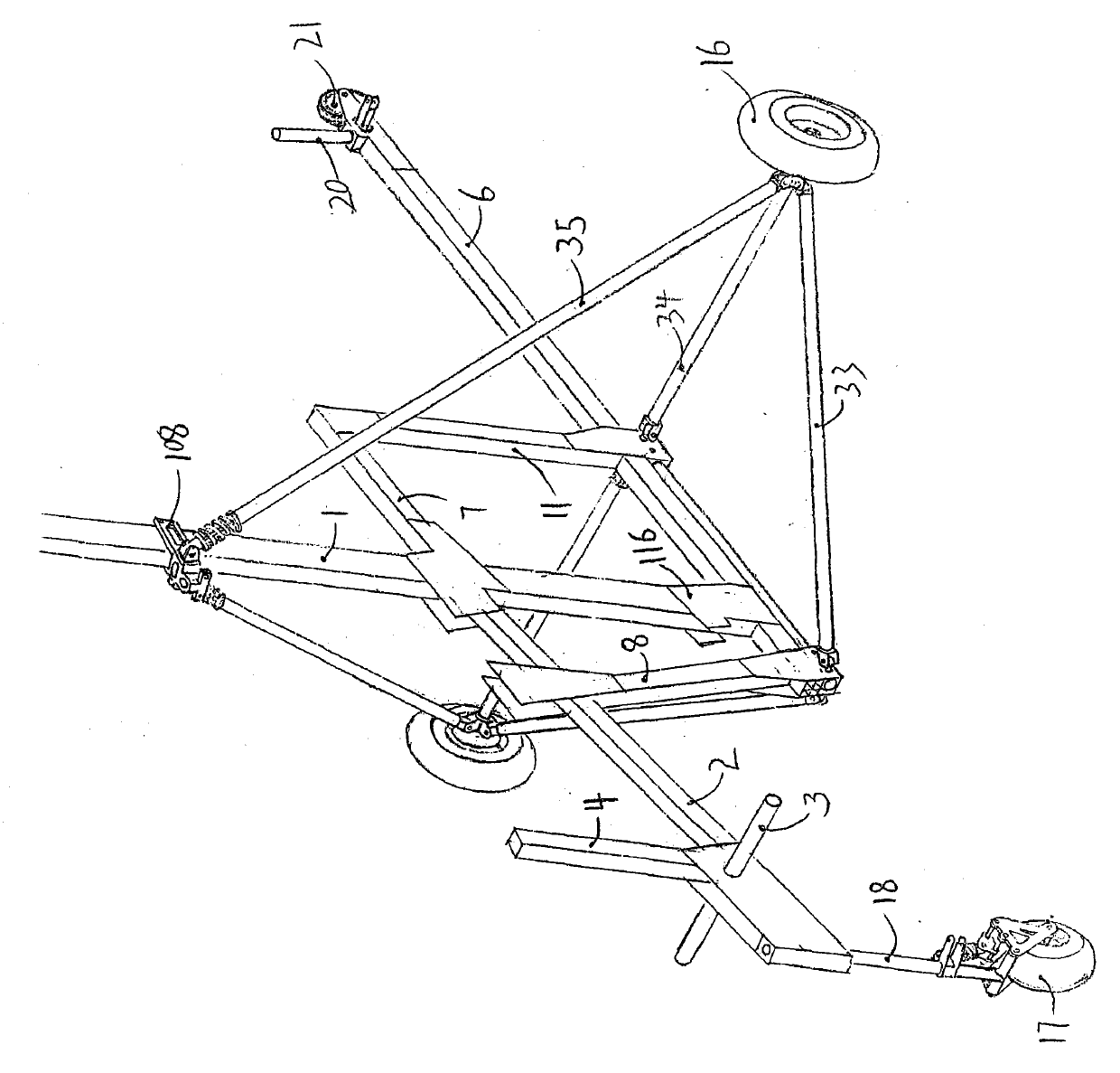
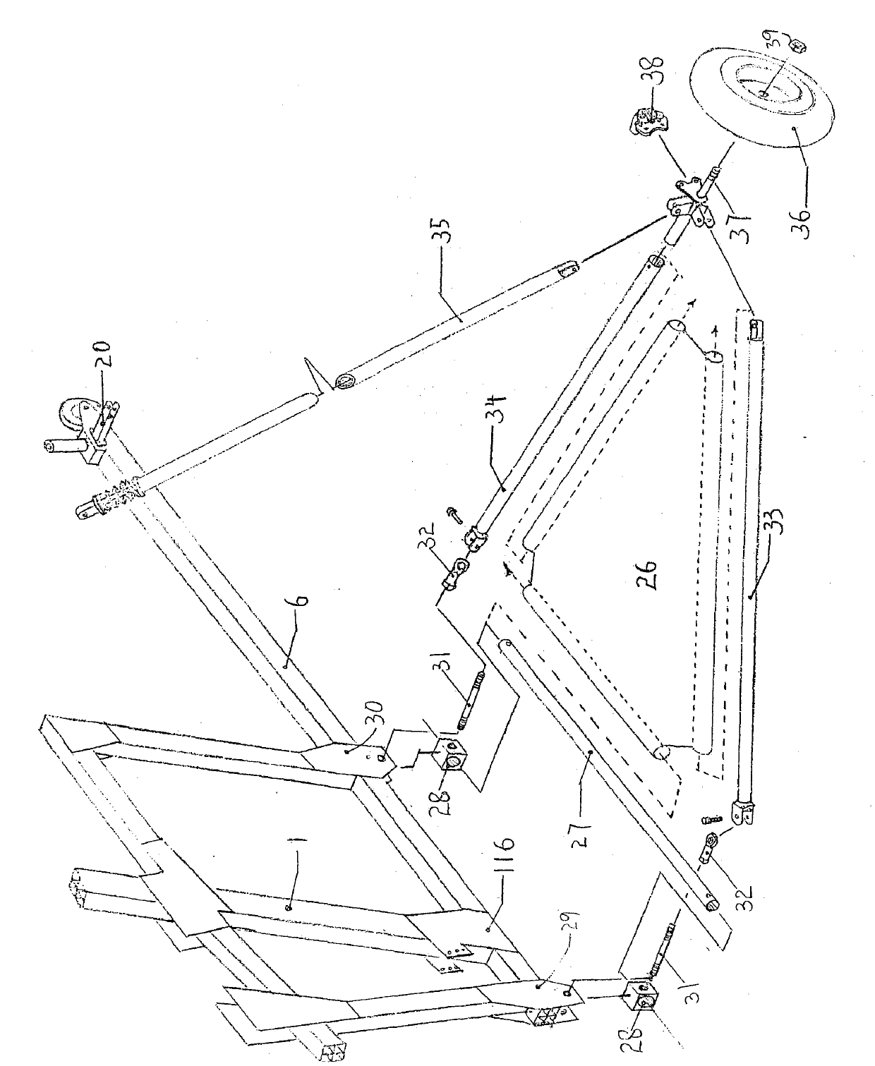
[0142] Embodiment two: if image 3 , Figure 4 , Figure 5 As shown, the fuselage part of the single hand-controlled rotorcraft of this embodiment is mainly composed of two parts, the fuselage main support and the three-point frame type independent shock-absorbing support mechanism with the propeller reaction force balance device.

[0143] Such as image 3 As shown, the fuselage main support adopts the positive three-point landing gear fuselage with a high center of gravity, adopts a front steering wheel 17 to be placed in the front, and is formed by the front horizontal support rod 33, the rear horizontal support rod 34, and the lateral support rod 35 through the middle two sides. And the three-point frame type independent shock-absorbing support mechanism that left and right support wheels 16 form is used as lateral support, and the lateral support bar 35 support of its both sides is connected on the upper steering joint base 108 both sides on the upper position of column ...

Embodiment 3

[0147] Embodiment three: as Image 6 , Figure 7 As shown, the rotor head mechanism of the single hand-controlled rotorcraft of this embodiment is composed of three parts: a splint-type propeller hub mechanism with internal variable pitch, a main structure of the rotor shaft, and a rotor connection and installation part.

[0148] Such as Image 6 As shown, the upper propeller hub surface 53 and the lower propeller hub surface 54 are two symmetrical elongated splints, the periphery of the two is provided with corresponding bolt connection holes, and the center of the two is processed with a vertically penetrating double-row ball The mounting hole of the bearing 55 is centered on the mounting hole of the double-row ball bearing 55, along the center line of the upper paddle hub surface 53 and the lower paddle hub surface 54 toward each end, each corresponding to a vertically penetrating upper paddle hub surface 53 and the mounting hole of the variable pitch joint bearing 56 on ...


PUM


Abstract

The invention provides a single-man manual-control rotorcraft which is composed of a rotorcraft body, a rotor shaft cantilever tilt structure, a full-manual-control mechanism and a rotor head mechanism having an internal variable distance function. The rotorcraft body has a high-gravity center normal-three-point undercarriage structure, wherein the main rotorcraft body consists of a vertical column, a front beam, a back beam, an engine bracket and a front support beam. A steering wheel is arranged right ahead and empennages are arranged at the back. A driver seat and an engine are respectively at the front and the back of the vertical column. In the rotorcraft, a push-type propeller provides power and a three-point frame-type individual damping support mechanism having a rotor reactive force balancing device is used for balancing the reactive force generated to the rotorcraft body by air during operation of the rotor, so that the rotorcraft is improved in takeoff and landing stability. By means of the full-manual-control mechanism having a steering linking function, a driver can complete the operations comprising distance change of the rotor, rotor shaft tilt, flying direction turning and braking just like driving a motorbike.

Description

technical field [0001] The invention relates to an aircraft among aviation aircraft, in particular to a fully hand-operated single-person hand-controlled rotorcraft. Background technique [0002] With the increasingly congested ground traffic, aircraft will become the inevitable development direction of three-dimensional traffic in the near future, and the rotorcraft has a very short takeoff and landing distance, so it does not have high requirements for the site. When a fault occurs, its spin landing function is better than that of a helicopter. It is safer, and some rotorcraft with pre-rotation function have the same vertical take-off function as helicopters. Since the structure is much simpler than conventional helicopters or even fixed-wing aircraft, the failure rate is also very low. Therefore, such aircraft must will become more and more popular. [0003] It has been more than 90 years since Silva invented the rotorcraft in 1923 and succeeded in 1925. The rotorcraft h...

Claims


Application Information

Patent Timeline
IPC IPC(8): B64C27/02B64C27/54
Inventor 王略
Owner 王略
Why Eureka
Try Eureka