A prism optical system

An optical system and prism technology, which is applied in the field of imaging optical system based on prism elements, can solve problems such as complex structures, and achieve the effects of small volume, long exit pupil distance, and simple structure

Active Publication Date: 2018-06-26
LUOYANG INST OF ELECTRO OPTICAL EQUIP OF AVIC
View PDF7 Cites 2 Cited by
  • Summary
  • Abstract
  • Description
  • Claims
  • Application Information

AI Technical Summary

Problems solved by technology

[0004] The purpose of the present invention is to provide a prism optical system to solve the problem of complex structure of the traditional coaxial symmetric imaging optical system

Method used


Image

  • A prism optical system
  • A prism optical system
  • A prism optical system

Examples


Embodiment Construction

[0034] The present invention will be described in further detail below in conjunction with the accompanying drawings.

[0035] Relay Imaging System Embodiment

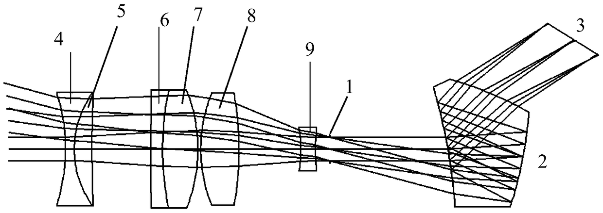
[0036] Such as figure 1 The relay imaging system shown as a whole includes two parts: one part is a telescopic optical system, and the other part is a prism optical system.

[0037] For the prism optical system, the optical parameters of the prism optical system are: entrance pupil diameter: 8mm, field of view: 24°; the working band of the prism optical system is 480nm~644nm; CCD parameters are: pixel size: 4.67μm×4.67 μm, number of pixels: 1024×768.

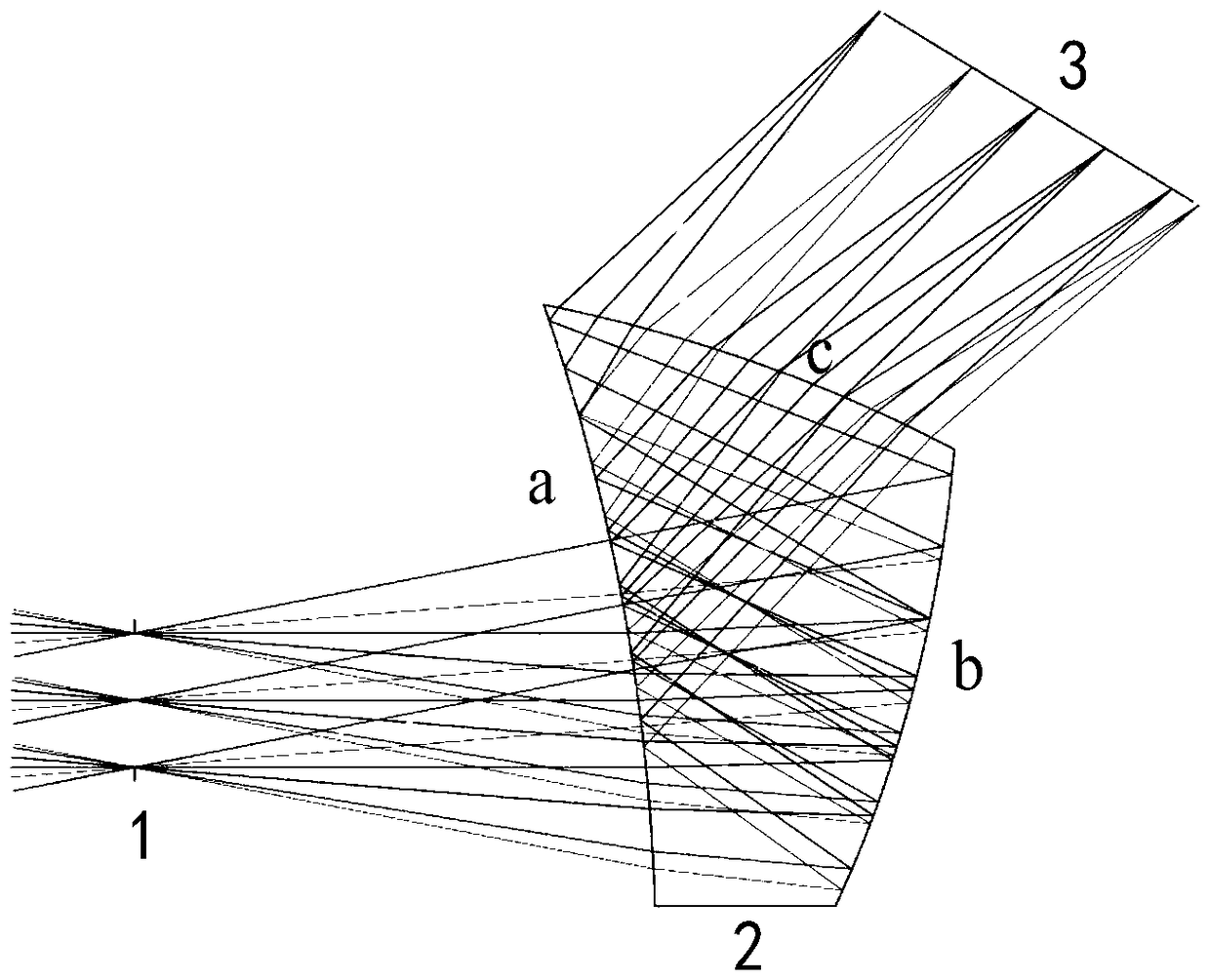
[0038] Such as figure 2 As shown, the imaging part of the prism optical system is composed of a prism. Aperture stop 1, prism element 2 and image surface 3 are sequentially distributed along the light transmission direction from the object side to the image side, wherein the prism 2 includes three optical surfaces ,Such as figure 2 As shown, they are the first sur...


PUM


Abstract

The invention relates to a prism optical system. The system comprises a prism. The prism comprises three optical surfaces. The first surface is a spherical face. The second surface is a free curved surface. The third surface is a diffraction face. Incident ray generated by an object firstly is transmitted through the first surface, then is sequentially reflected on the second surface and the first surface, and finally is transmitted out of the prism through the third surface. Design is achieved just through one prism optical element, common optical glass or optical plastics can be selected as materials of the prism, and the optical system is simple in composition, small in size, low in weight and low in cost; the image plane size and the field angle of the optical system are large. The prism element comprises the three optical surfaces, light is sequentially transmitted, reflected, totally reflected and transmitted among the three surfaces of the prism element, monochromatic aberration and compound-color aberration are well corrected, the optical system is good in imaging quality, and meanwhile the optical system has the advantages of being simple in structure and easy to assemble.

Description

technical field [0001] The invention relates to a prism optical system, in particular to an imaging optical system based on a prism element. Background technique [0002] With the development and extensive application of miniaturized photoelectric imaging components and micro image sources, optical systems used in cameras, video recorders, projectors, etc. are also required to have smaller volume, weight and lower cost. [0003] In the traditional coaxial symmetric imaging optical system, the optical elements are distributed sequentially on the optical axis, and its ability to compress the volume of space is limited. For axial chromatic aberration and vertical chromatic aberration, it is inevitable to use several groups of lens elements or several lens elements with special surface shapes for aberration correction, which directly leads to an increase in the complexity and cost of assembly. Contents of the invention [0004] The purpose of the present invention is to provi...

Claims


Application Information

Patent Timeline
Patent Type & Authority Patents(China)
IPC IPC(8): G02B17/08G02B27/00
CPCG02B17/0804G02B17/0884G02B27/0025
Inventor 王合龙陈建发
Owner LUOYANG INST OF ELECTRO OPTICAL EQUIP OF AVIC
Why Eureka
Try Eureka