Head-mounted display device

A technology of head-mounted display and equipment, which is applied in the direction of electrical equipment housing/cabinet/drawer, housing with display/control unit, portable housing, etc.

Active Publication Date: 2016-03-09
SAMSUNG ELECTRONICS CO LTD
View PDF5 Cites 42 Cited by
  • Summary
  • Abstract
  • Description
  • Claims
  • Application Information

AI Technical Summary

Problems solved by technology

Therefore, the inconvenience caused by the user having to

Method used


Image

  • Head-mounted display device
  • Head-mounted display device
  • Head-mounted display device

Examples


Embodiment Construction

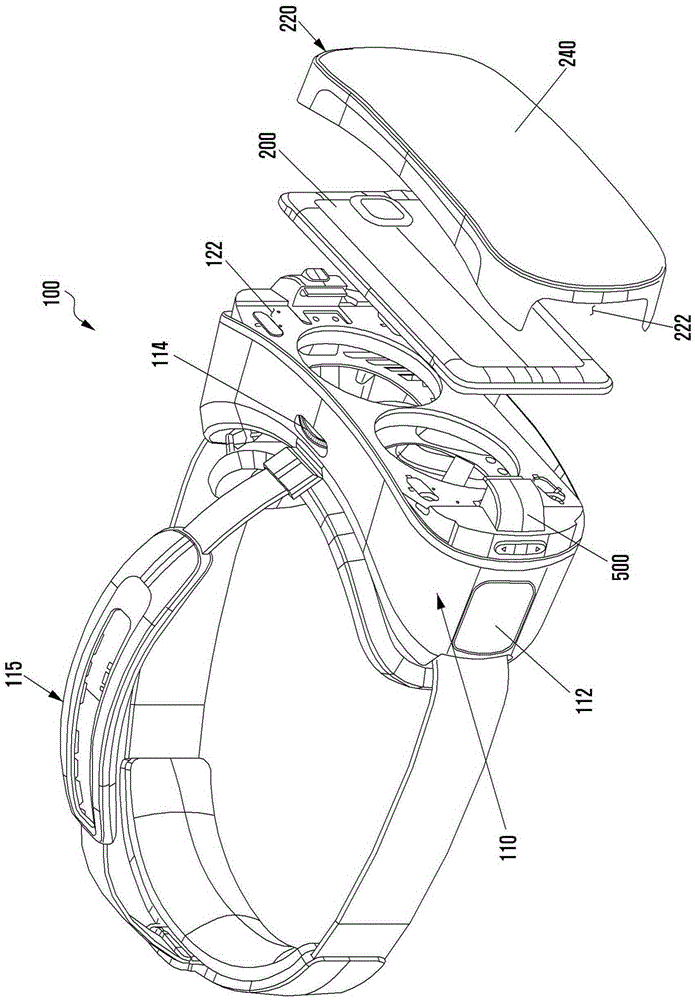
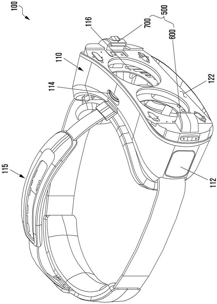
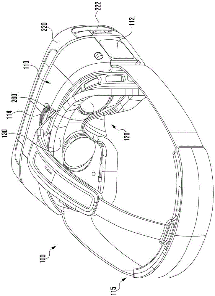
[0029] In this patent document, the following discussed Figure 1 to Figure 18 And the various embodiments used to describe the principles of the present disclosure are given by way of example only, and should not be construed as limiting the scope of the present disclosure in any way. Those skilled in the art will understand that the principles of the present disclosure may be implemented in any suitably arranged mobile devices and head-mounted devices. The present disclosure will be described below with reference to the accompanying drawings. The present disclosure can have various embodiments, and modifications and variations can be made thereto. Accordingly, the present disclosure will be described in detail with reference to specific embodiments illustrated in the accompanying drawings. However, it should be understood that this is not intended to limit the present disclosure to specific forms, but the present disclosure should be construed to cover all modifications, e...


PUM


Abstract

A head-mounted display device is provided. The head-mounted display device includes: a frame having one surface formed to face a user's face; a wearing part formed to be coupled to at least a part of the frame so as to allow the frame to be fixed to the face; a mounting part formed in a cavity structure so that an external electronic device is capable of being mounted on the other surface of the frame; and one or more fastening parts that fix the external electronic device to the mounting part, wherein the fastening parts has an inclined opening angle.

Description

technical field [0001] Various embodiments of the present disclosure relate to head-mounted display devices. Background technique [0002] Recently, various electronic devices have been developed in forms that can be worn directly on the body. Such devices are often referred to as wearable electronics. [0003] Examples of wearable electronic devices worn on a part of the body include: head-mounted display (HMD) devices worn on the user's head to display images, smart glasses, smart watches or wristbands, contact lens-type devices, ring-type devices , shoe equipment, clothing equipment and glove equipment. A wearable electronic device may take the form of a detachably attached part of the body or clothing. Specifically, the HMD may be formed in a goggle shape or a glasses shape. [0004] Wearable electronic devices can improve portability and user utilization due to being worn directly on the body. [0005] The display of the HMD device is capable of outputting an image...

Claims


Application Information

Patent Timeline
IPC IPC(8): G02B27/01
CPCG02B27/0176G02B2027/0154G02B2027/0169G02B2027/0136G02B2027/0156G06F1/163H05K5/0004H05K5/0017H05K5/0086H05K5/0204
Inventor 白種善尹硕振王相珍黃智晟金东眩李英振崔锺哲
Owner SAMSUNG ELECTRONICS CO LTD
Why Eureka
Try Eureka