Semi-automatic electrical equipment dust removal cleaner

A technology of electric equipment and cleaners, which is applied in the direction of removing smoke and dust, chemical instruments and methods, cleaning methods and utensils, etc., and can solve problems such as prone to dead spots in scrubbing, limited scrubbing height, time-consuming and laborious, etc.

Active Publication Date: 2016-03-30
STATE GRID SHANDONG ELECTRIC POWER COMPANY WEIFANG POWER SUPPLY +1
View PDF8 Cites 3 Cited by
  • Summary
  • Abstract
  • Description
  • Claims
  • Application Information

AI Technical Summary

Problems solved by technology

Before the arrival of spring and autumn every year, rain and fog increase. In order to prevent flashover accidents caused by dirt and dust on power equipment, the porcelain parts (mainly insulators) of power equipment need to be dust-removed and cleaned, and then painted. Anti-fouling flash paint, this work requires a lot of manual work, and the staff wipes it bit by bit with a rag in their hands. The workload is very heavy and the intensity of fatigue is very high.
Moreover, it is inconvenient for the staff to stand and move when cleaning on the equipment, so they can only work with one hand, and the other hand must hold the porcelain column to ensure personal safety and prevent falling from high altitudes. If you can touch the equipment at close range, you will inhale a large amount of dust at the same time, which will also cause considerable damage to your health.
[0003] At present, there is a device on the market that uses the extension rod to lift the rag into the air to scrub the power system equipment, which can solve the problem of dust inhalation or contamination due to the traditional scrubbing method being too close to the power system equipment, and has a better protective effect. , to ensure the health of the operator, but this scrubbing equipment also has the following disadvantages: 1, because the rag is lifted into the air by the extension rod for scrubbing, the scrubbing strength of the rag is greatly reduced, resulting in unclean scrubbing; 2. 1. The operation method of usin

Method used


Image

  • Semi-automatic electrical equipment dust removal cleaner
  • Semi-automatic electrical equipment dust removal cleaner
  • Semi-automatic electrical equipment dust removal cleaner

Examples


Embodiment Construction

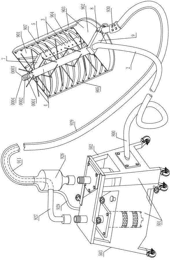
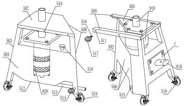
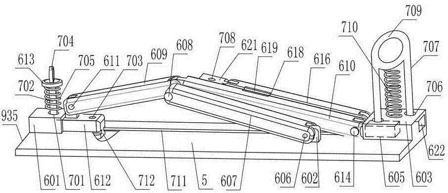
[0028] As shown in the figure, this semi-automatic power equipment decontamination cleaner includes a cleaning head 3 driven by a power unit 1 through a transmission hose 2. The cleaning head includes a vertically arranged rotating brush 4, and one side of the rotating brush is covered with a horizontal A protective cover 5 with a C-shaped cross-section, a handle 6 is fixed on the outside of the protective cover, and a horizontally extending upper rod 7 is fixed on the inner upper end of the protective cover. The end of the upper rod can only rotate with the upper end of the rotary brush through the upper connecting device. The lower end of the inner side of the cover is hinged with a lower rod 9 that can swing up and down through a horizontal shaft 8. The lower rod is rotatably matched with the lower end of the rotary brush through the lower connecting device, and the lower rod is also inserted and fitted with the lower end of the rotary brush through the lower connecting devic...


PUM


Abstract

The invention discloses a semi-automatic electrical equipment dust removal cleaner which comprises a cleaning head driven by a transmission hose through a power device. The cleaning head comprises a rotary brush which is arranged vertically. One side of the rotary brush is covered with a protection cover with the cross section being in a C shape. A handle is fixedly arranged outside the protection cover. An upper rod extending transversely is fixedly arranged at the upper end of the inner side of the protection cover. The end of the upper rod is in running fit with the upper end of the rotary brush through an upper connection device. A lower rod capable of swinging up and down is hinged to the lower end of the inner side of the protection cover through a horizontal shaft. The lower rod is in running fit with the lower end of the rotary brush through a lower connection device. The semi-automatic electrical equipment dust removal cleaner has the advantages that the structure is reasonable, scrubbing can be completed rapidly according to the shape of equipment to be scrubbed, and switching between a close-distance scrubbing mode and a long-distance scrubbing mode can be achieved freely and rapidly without changing the position where an operator is located; the scrubbing angle can be adjusted freely, stubborn stains can be wiped off, no dead corner exists during scrubbing, and time and labor are saved; the protectiveness for the scrubbing operator is good, the scrubbing operator is prevented from inhaling dust or being contaminated by the dust, and the situation that the dust enter the eyes of the operator is avoided; the wiped dust and dirt are prevented from falling on the equipment below the cleaner, the cleaner is free of the limitation of the scrubbing height, the scrubbing can be completed independently by one person, and the scrubbing effect is good.

Description

technical field [0001] The invention relates to a semi-automatic power equipment decontamination cleaner. Background technique [0002] At present, cleaning and decontamination of power equipment in the power system is a very heavy and repetitive work, and it also has certain harm to the health of the staff. Before the arrival of spring and autumn every year, rain and fog increase. In order to prevent flashover accidents caused by dirt and dust on power equipment, the porcelain parts (mainly insulators) of power equipment need to be dust-removed and cleaned, and then painted. Anti-fouling flashover coating, this work requires a lot of manual work, and the staff wipes it bit by bit with a rag in their hands. The workload is very heavy and the intensity of fatigue is very high. Moreover, it is inconvenient for the staff to stand and move when cleaning on the equipment, so they can only work with one hand, and the other hand must hold the porcelain column to ensure personal sa...

Claims


Application Information

Patent Timeline
IPC IPC(8): B08B1/04B08B3/02B08B15/04B08B1/00
CPCB08B1/00B08B1/002B08B1/006B08B1/04B08B3/02B08B15/04
Inventor 刘继君邱金海张涛王思城孙延栋
Owner STATE GRID SHANDONG ELECTRIC POWER COMPANY WEIFANG POWER SUPPLY
Why Eureka
Try Eureka