Switching power device

A switching power supply and switching technology, which is applied in the direction of output power conversion devices, electrical components, and adjustment of electrical variables, can solve problems such as abnormal loss, influence, and exceeding withstand voltage, and achieve the continuous effect of preventing self-excited oscillation

Active Publication Date: 2016-04-13
TDK CORPARATION
View PDF6 Cites 2 Cited by
  • Summary
  • Abstract
  • Description
  • Claims
  • Application Information

AI Technical Summary

Problems solved by technology

In this case, the Vds withstand voltage of the main switches Q1 and Q2 may be exceeded
In addition, between the output voltage plus the voltage of the electromotive force of the inductor L1 is applied to the Vds of the commutation side MOS-FETQ4 at the time of shutdown, and is also applied to the Vgs of the rectification side MOS-FETQ3, which may exceed the respective withstand voltages
[0034] In addition, there may be various disadvantages such as abnormal loss caused by unexpected current flow, and abnormal heating due to this, influence on other power sources connected in parallel as energy sources, or influence on the battery

Method used


Image

  • Switching power device
  • Switching power device
  • Switching power device

Examples


no. 1 Embodiment approach

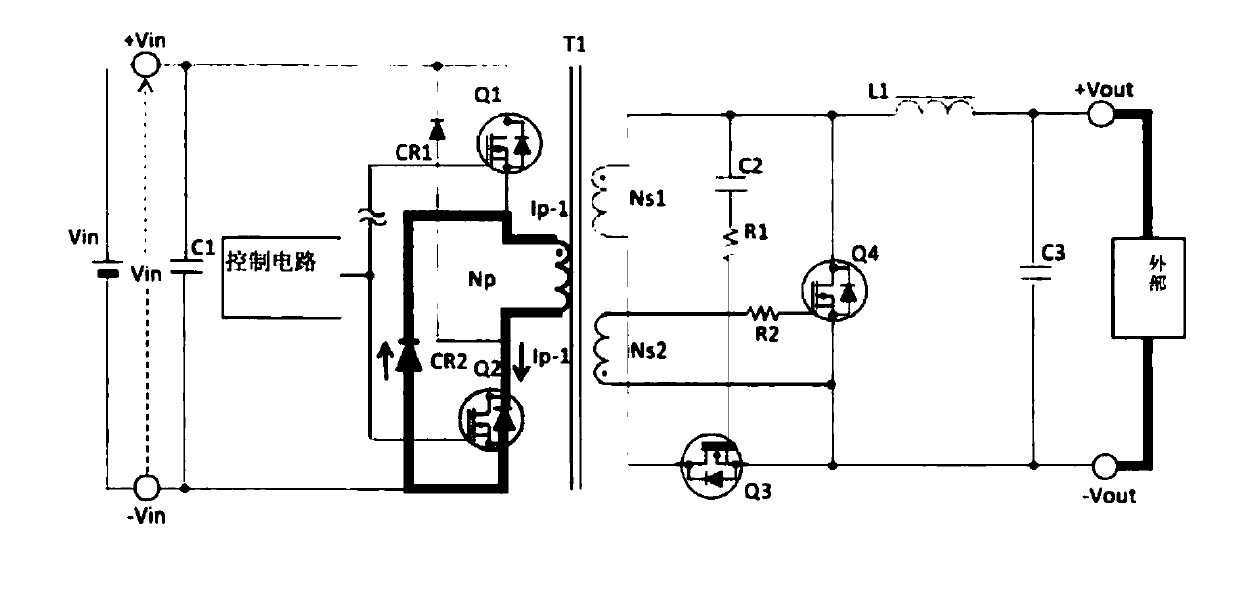
[0058] The circuit configuration and figure 1 The switching power supply devices shown are the same, only the output pulse of the control circuit is different. Figure 6 It is a figure which shows the output pulse of the control circuit of this embodiment. Figure 7 It is a circuit diagram showing the principle of the switching power supply device of this embodiment. Use the following figure 1 , Figure 6 , Figure 7 , the switching power supply device of the first embodiment will be described.

[0059]Specifically, the switching power supply device of this embodiment has a main transformer that insulates the primary side from the secondary side, that is, has a primary side main winding Np, a secondary side main winding Ns1, and an auxiliary transformer that drives the commutation side MOS-FETQ4. Coil Ns2.

[0060] The polarities of the main winding Np on the primary side, the main winding Ns1 on the secondary side, and the auxiliary winding Ns2 of the main transformer T...

no. 2 Embodiment approach

[0071] Figure 8 It is a figure which shows 2nd Embodiment of the switching power supply apparatus of this invention. Figure 8 In FIG. 2 , elements such as the rectifying elements CR1 and CR2 are omitted for easy description of the present embodiment.

[0072] Figure 8 The switching power supply device shown, with respect to the first embodiment of the switching power supply device, further includes, as an additional circuit: a series circuit of a first capacitor (C10) and a first resistor (R11), which is connected to the driving circuit of the control circuit. Between the pulse output terminal and the control terminal of the second main switch; the second resistor (R10), connected between the drive power supply of the control circuit and the control terminal of the second main switch; and the first constant voltage A series circuit of an element (CR10) and a third rectifying element (CR11), wherein the negative pole of the first constant voltage element is connected to th...

no. 3 Embodiment approach

[0080] Figure 9 It is a figure which shows the 3rd Embodiment of the switching power supply apparatus of this invention. Figure 9 In FIG. 2 , elements such as the rectifying elements CR1 and CR2 are omitted for easy description of the present embodiment.

[0081] Figure 9 The switching power supply device shown, with respect to the first embodiment of the switching power supply device, further includes, as an additional circuit: a series circuit of a fourth rectifying element (CR21) and a third resistor (R25), connected to the control circuit Between the drive pulse output terminal and the control terminal of the second main switch, the anode of the fourth rectifier element is connected to the drive pulse output terminal; the second constant voltage element (CR22) and the fourth resistor (R26) A series circuit, connected between the connection point of the fourth rectifier element and the third resistor and the ground, the anode of the second constant voltage element is g...


PUM


Abstract

The invention discloses a cascading normal shock switching power supply, and is provided with a main transformer which is provided with a primary main coil (Np) and a secondary main coil (Ns1); a first main switch (Q1); a second main switch (Q2); a control circuit; a first rectification element (CR2), wherein the negative electrode is connected to a connection point of the first main switch (Q1) with the primary main coil (Np), and the positive electrode is connected to a low potential side of an input DC voltage; a second rectification element (CR1), wherein the positive electrode is connected to a connection point of the second main switch (Q2) with the primary main coil (Np), and the negative electrode is connected to a high potential side of the input DC voltage; and a rectification circuit in a mode of synchronization rectification. When there is a voltage at an output end and the switching operation of the first and second main switches are stopped, the control terminal of any one of the first and second main switches is set in a mode of continuously connection and a positively biased voltage is applied to the control terminal. According to the invention, the device can prevent the continuous self-oscillation of the output end when there is a voltage (energy source) at the output end.

Description

technical field [0001] The present invention relates to a switching power supply device that can be used in various electronic devices. The switching power supply device includes a cascade self-excited converter including a plurality of main switching elements, and a synchronous rectifying element including a rectifying switching element and a commutating switching element. Background technique [0002] In high-power switching power supplies, it is important to achieve high efficiency and low component heat generation. As one of the countermeasures, a switching element such as a MOS-FET with a large rated current and low resistance can be used as the main switch, which is useful because it can reduce the loss when the main switching element is turned on. However, in general, the on-resistance of a MOS-FET increases at a ratio of 2 to 2.5 powers with respect to a breakdown voltage. Therefore, it is necessary to use a MOS-FET with an extremely low withstand voltage. [0003]...

Claims


Application Information

Patent Timeline
Patent Type & Authority Applications(China)
IPC IPC(8): H02M3/338
CPCH02M3/285H02M3/33592H02M3/33546Y02B70/10
Inventor 王跃庆王红蕾
Owner TDK CORPARATION
Why Eureka
Try Eureka