Switching power supply unit

A switching power supply and switching technology, which is applied in the direction of output power conversion devices, electrical components, and adjustment of electrical variables, can solve problems such as abnormal loss, exceeding withstand voltage, and impact, and achieve the continuous effect of preventing self-excited oscillation

Active Publication Date: 2016-03-16
TDK CORPARATION
View PDF6 Cites 2 Cited by
  • Summary
  • Abstract
  • Description
  • Claims
  • Application Information

AI Technical Summary

Problems solved by technology

In this case, the Vds withstand voltage of the main switch Q1 may be exceeded
In addition, between the output voltage plus the voltage of the electromotive force of the inductor L1 is applied to the Vds of the commutation side MOS-FETQ4 at the time of shutdown, and is also applied to the Vgs of the rectification

Method used


Image

  • Switching power supply unit
  • Switching power supply unit
  • Switching power supply unit

Examples


Example Embodiment

[0044] Hereinafter, the form for implementing this invention is demonstrated in detail, referring drawings.

[0045] Figures 4 to 8 It is a figure which shows embodiment of the switching power supply apparatus of this invention.

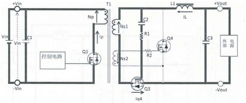
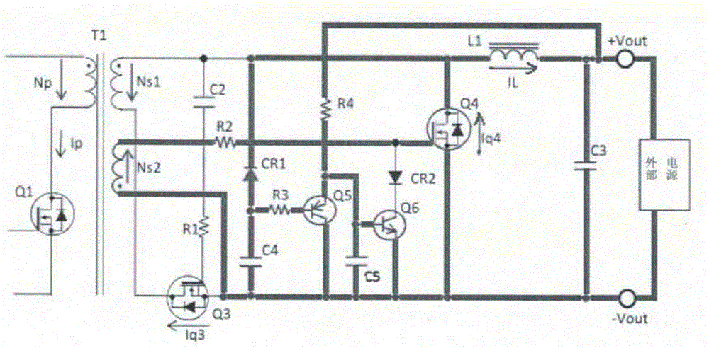
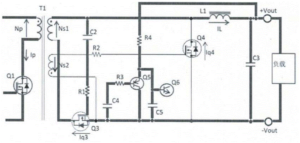
[0046] First, use Figure 4 The circuit configuration of the switching power supply device of the present embodiment will be described. Figure 4 The switching power supply device includes: a main transformer T1, which has primary side and secondary side insulation, a primary side main coil Np, a secondary side main coil Ns1, and an independently set auxiliary coil Ns2; a main switch Q1, which is in the input DC The voltage is connected in series with the primary side main coil Np; the control circuit generates / outputs the driving pulse for ON / OFF driving of the main switch Q1; the self-excited mode is composed of the rectification switch Q3 and the commutation switch Q4. A synchronous rectification circuit, in which the rectification switch Q3 i...


PUM


Abstract

The invention discloses a switching power supply unit which includes a rectifying unit with a synchronous rectifying mode. The rectifying circuit is provided with a rectifying switch connected in series with a secondary coil of a main transformer and conducted synchronously with a conduction period of a main switch; and a commutation switch connected in parallel with the secondary coil and conducted synchronously with the conduction period of the main switch. The switching power supply unit is provided with an auxiliary switching circuit. The auxiliary switching circuit detects the generated self-oscillation when voltage flows across an output end and the main switch stops switching, and enables the commutation switch to be turned off to prevent continuous self-oscillation. The switching power supply unit can prevent continuous self-oscillation generated when the main switch is turned off.

Description

technical field [0001] The present invention relates to a switching power supply device including a DC-DC converter that can be used in various electronic devices, and the switching power supply device includes a synchronous rectification element including a rectification switching element and a commutation switching element. Background technique [0002] In a switching power supply with low output voltage and high current, a synchronous rectification circuit in which the rectification element is replaced with a MOS-FET from a diode can reduce the conduction loss of the rectification part, which is advantageous in terms of efficiency and component heat generation. During the synchronous rectification operation of a synchronous rectification circuit having a rectification switching element (i.e. rectification side MOS-FET) and a commutation switching element (i.e. commutation side MOS-FET), the ON of the rectification side MOS-FET and the primary side main switch The drive si...

Claims


Application Information

Patent Timeline
IPC IPC(8): H02M3/335
CPCH02M3/285H02M3/335H02M3/33592Y02B70/10H02M3/33546
Inventor 王跃庆王红蕾
Owner TDK CORPARATION
Why Eureka
Try Eureka