Longitudinal cooler system for laser crystal

A technology for coolers and lasers, which is applied in the direction of laser cooling devices, lasers, laser components, etc., can solve the problems of large temperature difference of coolers, unreasonable design of coolers, and uneven temperature distribution, so as to ensure normal operation and maintain uniformity, reducing the effect of thermal gradients

Inactive Publication Date: 2016-05-11
INST OF APPLIED ELECTRONICS CHINA ACAD OF ENG PHYSICS
View PDF5 Cites 7 Cited by
  • Summary
  • Abstract
  • Description
  • Claims
  • Application Information

AI Technical Summary

Problems solved by technology

The design of the laser crystal cooler currently used is not reasonable, the temperature difference of the cooler is large, the temperature distribution is uneven, and the thermal gradient and thermal stress inside the laser crystal are large, which affects the normal operation of the laser system

Method used


Image

  • Longitudinal cooler system for laser crystal
  • Longitudinal cooler system for laser crystal

Examples


Embodiment 1

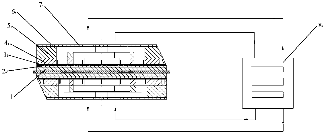
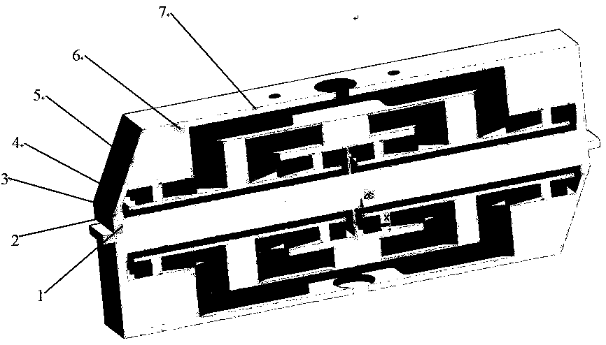
[0028] Such as Figure 1-Figure 2 As shown, the longitudinal cooler system for laser crystals of the present invention includes an upper cover plate layer 1, a heat dissipation layer 2, a small hole water separation plate layer 3, a width water separation plate layer 4, a cooling water merging layer 5, an auxiliary Welding sheet layer 6, bottom cover layer 7, temperature control cooling equipment;

[0029] The upper cover plate layer 1, the heat dissipation layer 2, the small hole water separation plate layer 3, the width water separation plate layer 4, the cooling water merging layer 5, the auxiliary solder plate layer 6 and the bottom cover plate layer 7 are stacked in sequence from bottom to top The upper and lower layers are fastened and sealed by welding; the auxiliary solder sheet layer 6 and the bottom cover layer 7 have a common water inlet and a total water outlet, and the total water inlet and temperature control of the bottom cover layer 7 The water outlet of the r...

Embodiment 2

[0043] Embodiment 2 is basically the same in structure and implementation as Embodiment 1, the main difference being:

[0044] The upper cover layer 1, the heat dissipation layer 2, the small hole water separation layer 3, the width water separation layer 4, the cooling water merging layer 5, the auxiliary solder sheet layer 6 and the bottom cover layer 7 adopt a thermal conductivity of 350W / (m·K) made of metal material, the contact surface of each layer is a mirror surface with a flatness equal to 20μm before welding.

[0045] The lower surface of the upper cover layer 1 is a mirror surface with a flatness equal to 8 μm.

[0046] The width of the water inlet hole and the water outlet hole of the small hole water separation plate layer 3 is equal to 400um, the width of the heat dissipation channel of the heat dissipation layer 2 is equal to 400um, the length of the small hole is equal to 1.2mm, and the length and width ratio of a single heat dissipation channel It is equal t...

Embodiment 3

[0051] Embodiment 3 is basically the same in structure and implementation as Embodiment 1, the main difference is:

[0052] The upper cover plate layer 1, the heat dissipation layer 2, the small hole water separation plate layer 3, the width water separation plate layer 4, the cooling water merging layer 5, the auxiliary solder plate layer 6 and the bottom cover plate layer 7 adopt a thermal conductivity of 400W / (m·K) made of metal material, the contact surface of each layer is a mirror surface with a flatness equal to 10μm before welding.

[0053] The lower surface of the upper cover layer 1 is a mirror surface with a flatness equal to 6 μm.

[0054] The width of the water inlet hole and the water outlet hole of the small hole water separation plate layer 3 is equal to 300um, the length of the hole is equal to 0.9mm, the width of the heat dissipation channel of the heat dissipation layer 2 is equal to 300um, and the length and width ratio of a single heat dissipation channel...


PUM


Abstract

The invention provides a longitudinal cooler system for laser crystal. An upper cover plate layer, a heat dissipation layer, a small-hole water diversion plate layer, a width water diversion plate layer, a cooling water merging layer, an auxiliary soldering tag layer and a bottom cover plate layer of the longitudinal cooler system are stacked up from the bottom up in sequence; the layers are tightly sealed through a welding manner; and a water incoming channel and a water outgoing channel between the layers form cooling loops with a water outlet and a water inlet of a temperature control refrigeration device. A heat dissipation channel formed through layer-by-layer subdivision of the water incoming channel enables the upper cover plate layer to be cooled into a heat dissipation surface, the temperature distribution of which is uniform, so that heat generated by the laser crystal attached on the heat dissipation surface in the working process can be taken away efficiently, uniformity of transverse temperature of the laser crystal is kept, thermal gradient and thermal stress in the laser crystal are reduced, and normal work of the laser is ensured.

Description

technical field [0001] The invention belongs to the field of laser crystal cooling, in particular to a longitudinal cooler system for laser crystals. Background technique [0002] In the slab gain module laser system, in order to ensure the working performance of the laser system, it is necessary to solve the thermal management problem of the laser crystal; this requires a reasonable way to remove the heat generated during the laser crystal operation and maintain the lateral temperature of the laser crystal. Uniformity, so that the thermal gradient and thermal stress inside the laser crystal can be reduced. The design of the laser crystal cooler currently used is unreasonable, the temperature difference of the cooler is large, the temperature distribution is uneven, and the thermal gradient and thermal stress inside the laser crystal are large, which affects the normal operation of the laser system. Contents of the invention [0003] The technical problem to be solved by ...

Claims


Application Information

Patent Timeline
Patent Type & Authority Applications(China)
IPC IPC(8): H01S3/04H01S3/042
CPCH01S3/04H01S3/0407H01S3/042
Inventor 石勇唐淳胡浩高清松李密邬映臣雷军陈小明雒仲祥付波
Owner INST OF APPLIED ELECTRONICS CHINA ACAD OF ENG PHYSICS
Why Eureka
Try Eureka