Aircraft static strength test loading device

A technology of loading device and static strength, applied in the field of aircraft testing, can solve problems such as landing gear application

Active Publication Date: 2016-05-25
CHINA AIRPLANT STRENGTH RES INST
View PDF6 Cites 16 Cited by
  • Summary
  • Abstract
  • Description
  • Claims
  • Application Information

AI Technical Summary

Problems solved by technology

[0003] The purpose of the present invention is to provide a kind of aircraft static strength test loading device, solve or at least

Method used


Image

  • Aircraft static strength test loading device
  • Aircraft static strength test loading device
  • Aircraft static strength test loading device

Examples


Embodiment Construction

[0027] In order to make the objectives, technical solutions and advantages of the present invention clearer, the technical solutions in the embodiments of the present invention will be described in more detail below in conjunction with the drawings in the embodiments of the present invention. In the drawings, the same or similar reference numerals denote the same or similar elements or elements having the same or similar functions throughout. The described embodiments are some, but not all, embodiments of the invention. The embodiments described below by referring to the figures are exemplary and are intended to explain the present invention and should not be construed as limiting the present invention. Based on the embodiments of the present invention, all other embodiments obtained by persons of ordinary skill in the art without creative efforts fall within the protection scope of the present invention. Embodiments of the present invention will be described in detail below ...


PUM


Abstract

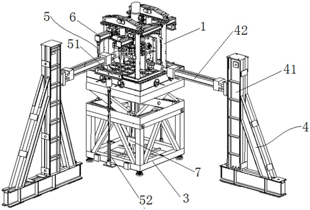
The invention discloses an aircraft static strength test loading device, and relates to the technical field of aircraft test. The aircraft static strength test loading device comprises an upper frame, a ball plate, a lifting platform and a horizontal restraint device, wherein the upper frame is used for connecting virtual wheels of an undercarriage; the ball plate comprises balls and a clamping plate, the clamping plate is provided with a plurality of ball grooves, the balls are arranged in the ball grooves, and the spherical surfaces of the balls protrude two opposite sides of the clamping plate in the thickness direction; the lifting platform is used for adjusting the height position of the upper frame; the horizontal restraint device is used for connecting the virtual wheels of the undercarriage and applying a horizontal restraint; the upper frame is installed on the lifting platform, and the ball plate is arranged between the upper frame and the installation surface of the lifting platform. The aircraft static strength test loading device has the advantages that the device is provided with the ball plate, and the balls are arranged on the ball plate to provide low rolling frictional resistance, so that the undercarriage is horizontally loaded and deformed without being restrained while a vertical load is applied.

Description

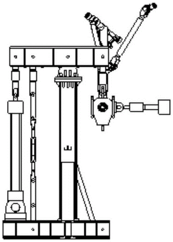
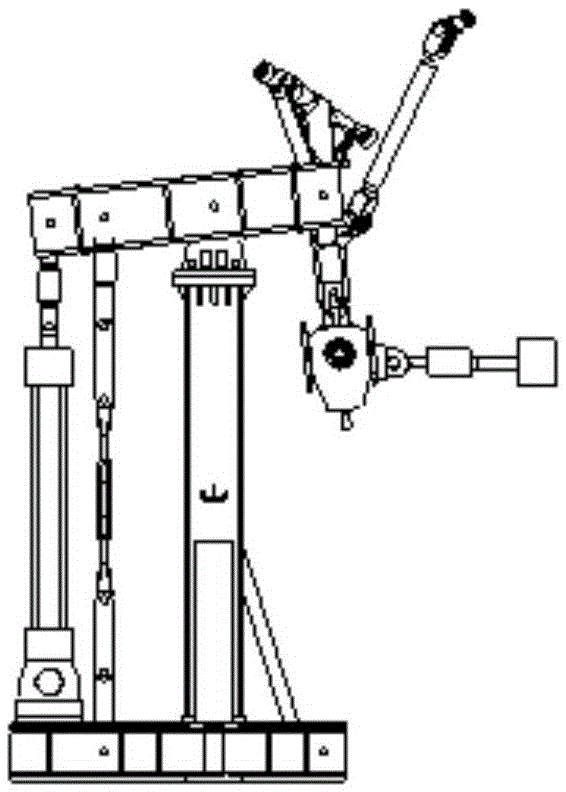
technical field [0001] The invention relates to the technical field of aircraft testing, in particular to an aircraft static strength test loading device. Background technique [0002] At present, the domestic full-scale aircraft static test landing gear loading and support mainly adopts the crowbar-column method, which can effectively apply the test load and meet the aircraft support requirements in the large-stiffness landing gear static test, but for high pillars and large deformation The landing gear of the landing gear, after the landing gear is loaded and deformed, will change the vertical load application direction of the landing gear and produce certain additional constraints when the landing gear is used as a support, see figure 1 , figure 2 . Contents of the invention [0003] The purpose of the present invention is to provide a static strength test loading device for an aircraft, which solves or at least alleviates at least one problem in the background techn...

Claims


Application Information

Patent Timeline
IPC IPC(8): G01M13/00
CPCG01M13/00
Inventor 严冲惠养红夏龙强宝平冯建民宋鹏飞
Owner CHINA AIRPLANT STRENGTH RES INST
Why Eureka
Try Eureka