New self-weight keyboard typing module

A keyboard, a new type of technology, applied in the field of new self-weight keyboard percussion modules, can solve the problems of inconvenient maintenance, difficult connection, narrow operation and assembly space, etc., to achieve convenient assembly, maintenance and operation, stable percussion force output, The effect of high test pass rate

Active Publication Date: 2018-10-02
珠海市运泰利自动化设备有限公司
View PDF5 Cites 0 Cited by
  • Summary
  • Abstract
  • Description
  • Claims
  • Application Information

AI Technical Summary

Problems solved by technology

There are many problems in the knocking bar load-bearing module currently used in the market, such as: the coordination between the electromagnet control circuit board and the knocking bar installation position, the wiring terminals on the PCB board are arranged on the corresponding knocking bar, and the After finishing the knocking rods, the wiring must be plugged between the knocking rods with a small gap. The space for operation and assembly is narrow, the connection is difficult, the maintenance is not convenient, and the PCB board cannot be taken out separately. If it needs to be taken out, all the knocking rods must be removed. The rod is removed; in addition, it is difficult to arrange the wires after the PCB board is connected.
After the above-mentioned line arrangement, the arrangement of the line body between the knocking rods is prevented. There is no fixing device, and the compression deformation of the line body is easy to generate tension, which will cause a gap between the rectified line body rebound and the movement of the electromagnet when the equipment is running. Interference, interference will cause additional resistance to the electromagnet-driven knocking body load round rod, resulting in jamming, resulting in a drop in test success rate

Method used


Image

  • New self-weight keyboard typing module
  • New self-weight keyboard typing module
  • New self-weight keyboard typing module

Examples


Embodiment Construction

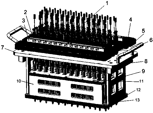
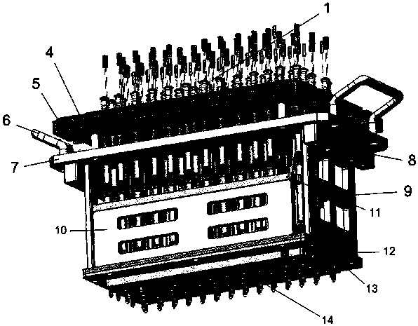
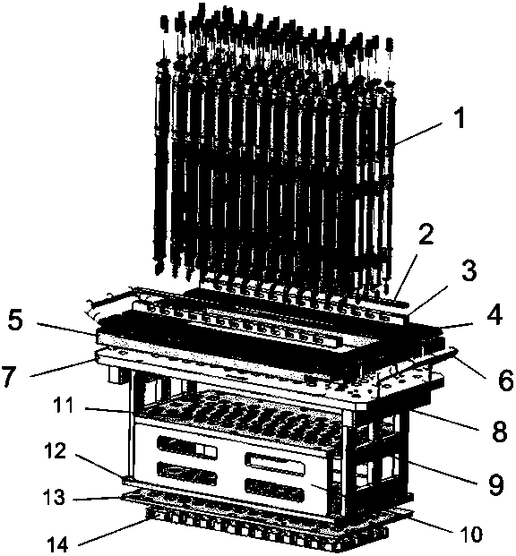
[0022] like Figure 1 to Figure 3 As shown, in the present embodiment, the present invention includes several knocking rods 1, PCB board 4, PCB board fixing frame 5 and electromagnet fixing plate 7, and several described knocking rods 1 are arranged on the fixed position of the electromagnet. On the plate 7, below the electromagnet fixing plate 7, there are guide plates 11 that are compatible with several knocking rods 1, and the PCB board fixing frame 5 is located above the electromagnet fixing plate 7, so that The PCB board fixing frame 5 is provided with placement holes, and the tops of several knock bars 1 pass through the placement holes, and the PCB board 4 is fixedly arranged on the PCB board fixing frame 5, and the PCB The plate 4 is provided with a through hole adapted to the placement hole.

[0023] In this embodiment, handles 6 are provided on both sides of the electromagnet fixing plate 7, and the handles 6 are angled handles.

[0024] In this embodiment, the PCB...


PUM


Abstract

The invention discloses a novel deadweight keyboard knocking module, aiming at providing a novel deadweight keyboard knocking module which enables operation of the whole equipment to be more safe, stable and efficient and enables maintenance of the equipment to be more simple and convenient. The novel deadweight keyboard knocking module includes a plurality of knocking sticks (1), a PCB (4), a PCB fixing rack (5) and an electromagnet fixing plate (7), wherein a guide plate (11) which is matched with the plurality of knocking sticks (1) is arranged below the electromagnet fixing plate (7); the PCB fixing rack (5) is arranged on the electromagnet fixing plate (7); placing holes are formed in the PCB fixing rack (5); the upper parts of the plurality of knocking sticks (1) penetrate through the placing holes; the PCB (4) is fixedly arranged on the PCB fixing rack (5); and through holes which are matched with the placing holes are formed in the PCB (4). The novel deadweight keyboard knocking module is applied to the technical field of the deadweight keyboard knocking module.

Description

technical field [0001] The invention relates to a striking device, in particular to a novel self-weight keyboard striking module. Background technique [0002] The keyboard knocking module is used to test the knocking of various built-in and external keyboard keys. There are many problems in the knocking bar load-bearing module currently used in the market, such as: the coordination between the electromagnet control circuit board and the knocking bar installation position, the wiring terminals on the PCB board are arranged on the corresponding knocking bar, and the After finishing the knocking rods, the wiring must be plugged between the knocking rods with a small gap. The space for operation and assembly is narrow, the connection is difficult, the maintenance is not convenient, and the PCB board cannot be taken out separately. If it needs to be taken out, all the knocking rods must be removed. The rod is removed; in addition, it is difficult to arrange the wires after the ...

Claims


Application Information

Patent Timeline
Patent Type & Authority Patents(China)
IPC IPC(8): G01R31/327
CPCG01R31/327
Inventor 阮惠鹏
Owner 珠海市运泰利自动化设备有限公司
Why Eureka
Try Eureka