Flange stacking device

A flange and conveying device technology, applied in the field of flange stacking devices, can solve the problems of increased production costs, low efficiency, and large volume

Active Publication Date: 2017-10-20
JIANGYIN HENGRUN RING FORGING
View PDF5 Cites 0 Cited by
  • Summary
  • Abstract
  • Description
  • Claims
  • Application Information

AI Technical Summary

Problems solved by technology

[0002] After the large flanges are processed and formed, after non-destructive testing and packaging, they need to be stacked in the storage warehouse to be processed out of the warehouse. When the flanges are stacked, usually in order to avoid mutual influence, they need to be isolated by placing pads. At present, the large flanges The stacking method usually uses a large crane plus a spreader, supplemented by manual cooperation, and the pads are also placed manually, which is not only inefficient, but also has a high cost and a large volume for a large crane. With the increase of labor cost, the production cost is increased

Method used


Image

  • Flange stacking device
  • Flange stacking device
  • Flange stacking device

Examples


Embodiment Construction

[0022] The present invention will be further described below in conjunction with the accompanying drawings and specific embodiments.

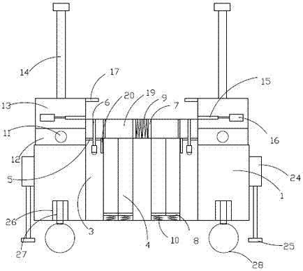
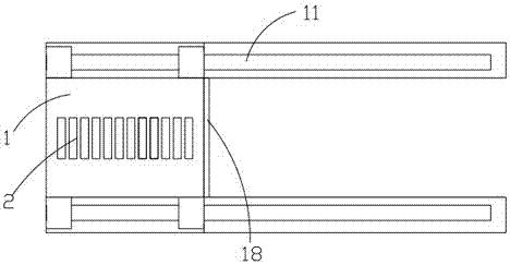
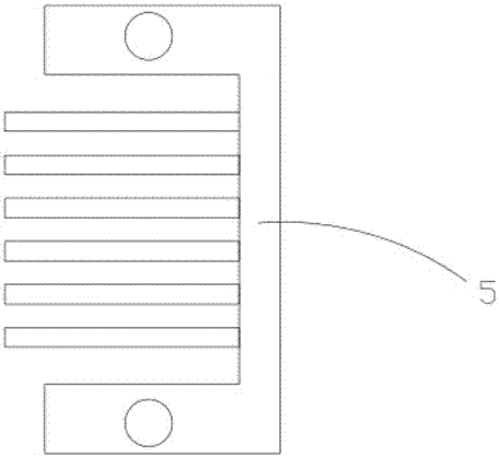
[0023] Such as Figure 1-Figure 5 As shown, the present invention discloses a flange stacking device, which includes a conveying track, a flange conveying frame 21 connected to the conveying track, and a stacking device moving along the conveying track. The traversing track 22 connected with the flange conveying frame 21, and several longitudinal moving tracks 23 connected with the traversing track 22, the stacking device includes a frame 1, and the bottom of the frame 1 is rotatably provided with a switch To the moving mechanism, the reversing moving mechanism includes push-off hydraulic cylinders 24 arranged on both sides of the frame, the piston rod of the push-off hydraulic cylinders 24 is arranged downwards and is connected with a support base 25, the frame 1 There are several wheel brackets 26 slidingly arranged on the bottom along the u...


PUM


Abstract

The invention provides a flange stack mounting device. The flange stack mounting device comprises a conveying rail, a flange conveying frame and a stacking device. The conveying rail comprises a transverse moving rail and a plurality of longitudinal moving rails; the stacking device comprises a rack, and a reversing movement mechanism is rotatably arranged at the bottom of the rack; a conveying device is arranged on the working face of the rack, and a filler strip storage conveying device is arranged in the rack and comprises filler strip storage conveying units which are symmetrically arranged on the left side and the right side of the rack; the filler strip storage conveying unit on each side comprises a filler strip lifting channel, a plurality of filler strip storage channels, a filler strip lifting mechanism and a pushing mechanism; and inlets communicated with the filler strip storage channels are formed in the lower portions of the filler strip lifting channels, filler strip outlets communicated with the filler strip lifting channels on the two sides are formed in the working face of the rack, and stacking mechanisms for automatically stacking filler strips and flanges are arranged on the left side and the right side of the rack. According to the stacking mechanisms, the large flanges can be automatically stacked, labor intensity is low, and the efficiency is high.

Description

technical field [0001] The invention relates to flange conveying equipment, in particular to a flange stacking device. Background technique [0002] After the large flanges are processed and formed, after non-destructive testing and packaging, they need to be stacked in the storage warehouse to be processed out of the warehouse. When the flanges are stacked, usually in order to avoid mutual influence, they need to be isolated by placing pads. At present, the large flanges The stacking method usually uses a large crane plus a spreader, supplemented by manual cooperation, and the pads are also placed manually, which is not only inefficient, but also has a high cost and a large volume for a large crane. With the increase of labor cost, the production cost has been improved. Contents of the invention [0003] The purpose of the present invention is to overcome the shortcomings of the above technologies, thereby providing a flange stacking device that can automatically stack l...

Claims


Application Information

Patent Timeline
Patent Type & Authority Patents(China)
IPC IPC(8): B65G57/32
CPCB65G57/32
Inventor 缪惠民周斌承刚卞晓磊曹磊吕澎沸
Owner JIANGYIN HENGRUN RING FORGING
Why Eureka
Try Eureka