Crankshaft type compressor valve plate structure

A compressor and valve plate technology, which is applied to liquid variable volume machinery, mechanical equipment, variable volume pump components, etc., can solve the problems of short service life, poor valve force, and easy breakage of the suction valve. , to achieve the effect of alleviating the rapid increase in airflow, simplifying the structure and reducing the cost

Inactive Publication Date: 2016-06-01
FENGHUA ZHEXING XINHUI REFRIGERATION EQUIP CO LTD
View PDF6 Cites 0 Cited by
  • Summary
  • Abstract
  • Description
  • Claims
  • Application Information

AI Technical Summary

Problems solved by technology

[0003] The shape of the suction valve plate of the valve plate is generally a long tongue shape, which will be bent repeatedly during the working process. The stopper is a single-point (or single-line) impact, so the force of this valve is poor and the service life is short. Once the compressor has a liquid hammer, the suction valve is more likely to break

Method used


Image

  • Crankshaft type compressor valve plate structure
  • Crankshaft type compressor valve plate structure
  • Crankshaft type compressor valve plate structure

Examples


Embodiment Construction

[0015] The present invention will be further described in detail below in conjunction with the accompanying drawings and embodiments.

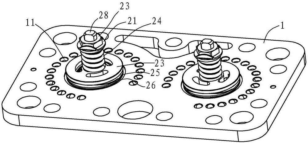
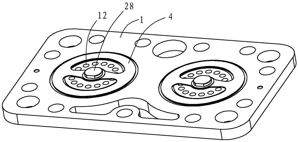
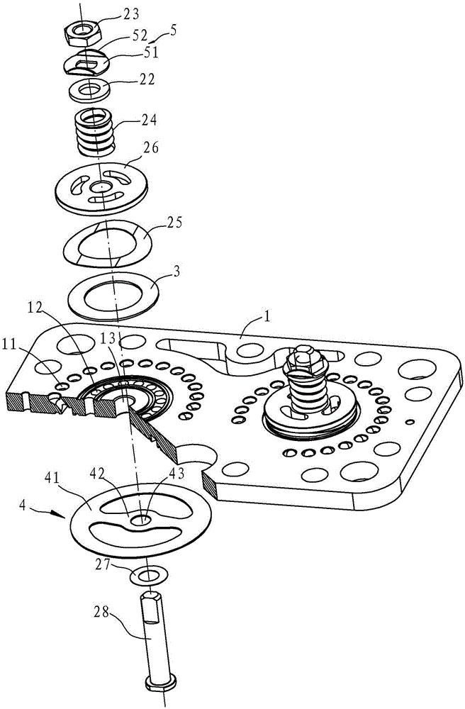
[0016] Such as figure 1 , figure 2 and image 3 As shown, the crankshaft compressor valve plate structure in this embodiment includes a valve plate 1, an exhaust valve plate 3 and a suction valve plate 4. The valve plate 1 has an exhaust hole 12 and an air suction hole 11, and the exhaust The valve plate 3 is arranged on the first surface of the valve plate 1 and can open and close the exhaust hole 12. The suction valve plate 4 is arranged on the second surface of the valve plate 1 and can open and close the air suction hole 11. The middle part of the valve plate 1 has The installation hole 13, the connecting member passes through the installation hole 13 to set the exhaust valve plate 3 and the suction valve plate 4 together on the valve plate 1; the exhaust hole 12 is arranged on the valve plate 1 in a ring shape and surrounds the instal...


PUM


Abstract

A crankshaft type compressor valve plate structure comprises a valve plate, exhaust valve sheets and air suction valve sheets. The valve plate is provided with exhaust holes and suction holes. The exhaust holes are annularly formed in the valve plate and surround mounting holes. Correspondingly, the exhaust valve sheets are provided with annular sealing faces. The suction holes are annularly formed in the valve plate and surround the exhaust holes. Correspondingly, the suction valve sheets are provided with annular sealing portions. The back face of each exhaust valve sheet is sequentially provided with a compression spring, a limiting device and a wavelike shrapnel from outside to inside. Compared with the prior art, the crankshaft type compressor valve plate structure has the beneficial effects that the situation that the gas flow is rapidly increased is relieved, and the exhaust valve sheets are protected against impact and breakage.

Description

technical field [0001] The invention relates to a crankshaft compressor component, in particular to a valve plate structure of the compressor. Background technique [0002] At present, the reed valve plate structure is the main valve plate structure widely used in common crankshaft compressors, such as Figure 4 As shown, the valve plate structure includes valve plate 1a, exhaust valve plate 5a, exhaust spring plate 4a, limiter 3a, spacer 7a, suction valve plate 6a and suction spring plate 8a, and valve plate 1a is provided with The exhaust hole 11a and the suction hole 12a, the screw 2a sequentially connect the spacer 7a, the stopper 3a, the exhaust spring piece 4a and one end of the exhaust valve piece 5a to the first surface of the valve plate 1a and use the nut 21a Fixed, the other end of the exhaust valve plate 5a is facing the exhaust hole 11a, one end of the suction valve plate 6a is fixed on the second surface of the valve plate with a cylindrical pin 61a through the...

Claims


Application Information

Patent Timeline
Patent Type & Authority Applications(China)
IPC IPC(8): F04B39/10
CPCF04B39/1046F04B39/102F04B39/1033
Inventor 林伦华刘铭刚
Owner FENGHUA ZHEXING XINHUI REFRIGERATION EQUIP CO LTD
Why Eureka
Try Eureka