Multi-level blade centrifugal wheel

A centrifugal wheel and blade technology, applied in the components of pumping devices for elastic fluids, non-variable volume pumps, machines/engines, etc., can solve problems such as stable operation, reduce pressure loss, and widen stable operation. range, the effect of improving the anti-cavitation performance

Inactive Publication Date: 2016-06-01
XIAN AEROSPACE PROPULSION INST
View PDF8 Cites 5 Cited by
  • Summary
  • Abstract
  • Description
  • Claims
  • Application Information

AI Technical Summary

Problems solved by technology

[0007] In order to solve the problem that the high-speed pumps in the prior art cannot work stably under low inlet pressure and wide range of variable working conditions, a centrifugal wheel with high efficiency and wide stable working range under partial working conditions is provided to reduce the pump's pressure in non-design working conditions. vibration levels for improved reliability

Method used


Image

  • Multi-level blade centrifugal wheel
  • Multi-level blade centrifugal wheel
  • Multi-level blade centrifugal wheel

Examples


Embodiment Construction

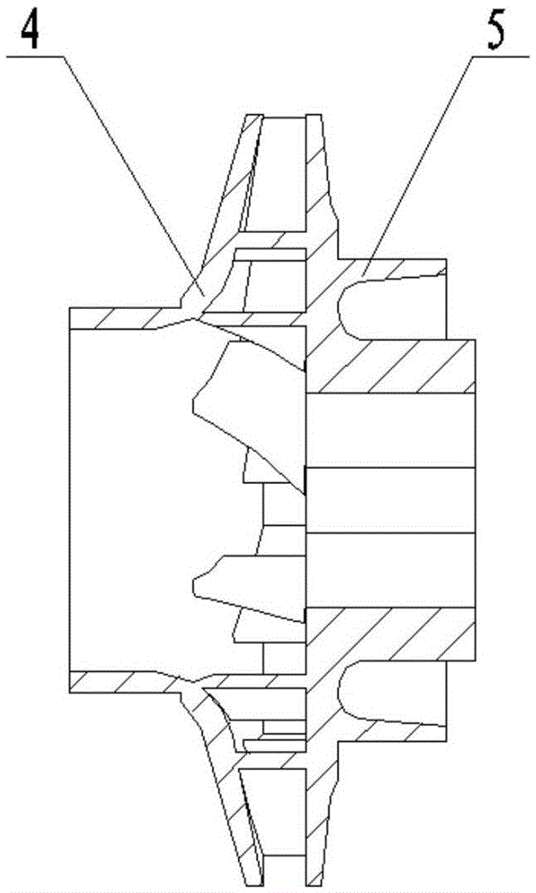
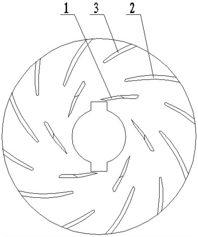
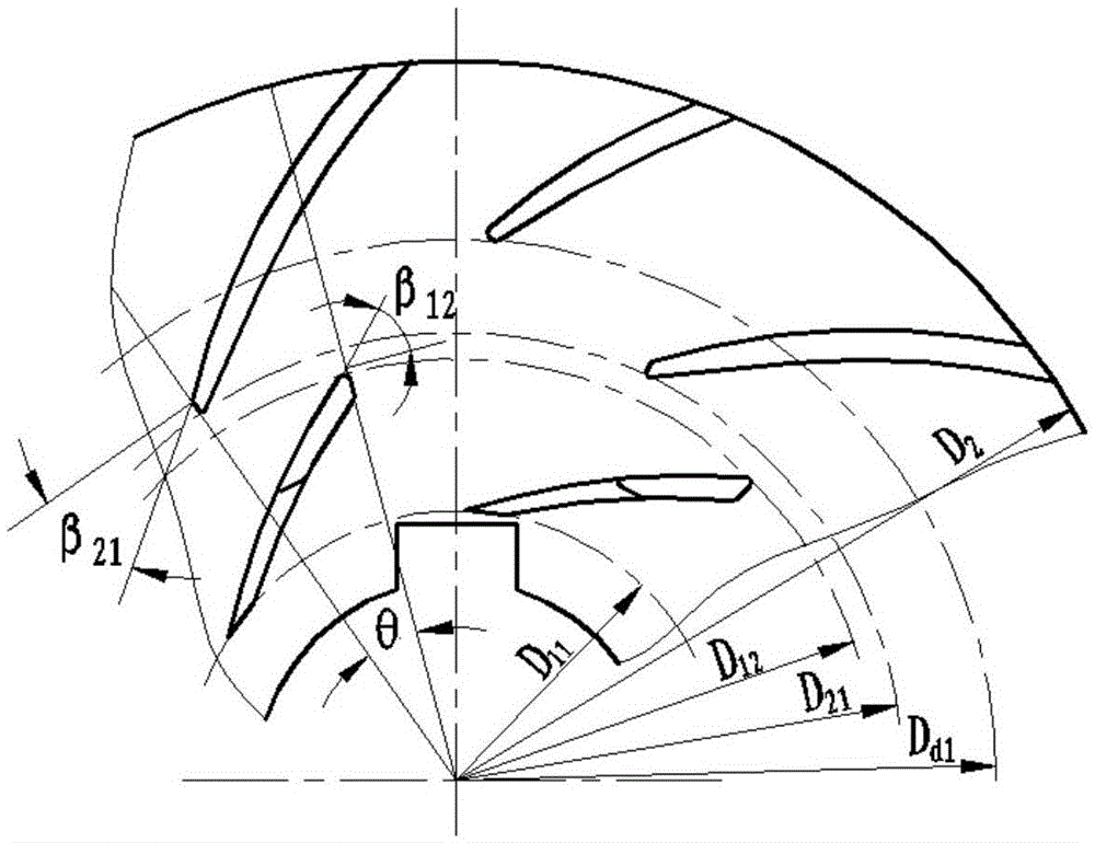
[0024] figure 1 It is a structural schematic diagram of the multi-stage blade centrifugal wheel of the present invention, which is also a preferred embodiment of the present invention. The first-stage blade 1, the second-stage blade 2 and the short blade 3 of the multi-stage blade centrifugal wheel of the present invention are integrally processed with the hub 5, and on one surface of the hub 5, a plurality of blades of the first-stage blade 1 follow the same The installation angle is arranged on the inner periphery, and multiple blades of the second-stage blade 2 are arranged on the periphery according to the same installation angle. The first-stage blades 1 and the second-stage blades 2 are alternately distributed step by step, and the short blades 3 are distributed on the second-stage blades. between. The first-stage blade 1 can adopt the same blade shape as the second-stage blade 2, and the first-stage blade outlet placement angle β 12 Greater than or equal to the second...


PUM


Abstract

The invention discloses a multi-level blade centrifugal wheel which comprises a front cover plate, multiple groups of blades and a hub, wherein the multiple groups of blades comprise first-level blades, second-level blades and short blades; multiple blades of the first-level blades are arranged at the inner circumference on one surface of the hub according to same setting angles; multiple blades of the second-level blades are arranged at the outer circumference according to same setting angles; the first-level blades and the second-level blades are alternatively distributed step by step; and the multiple short blades are distributed among the second-level blades. The centrifugal wheel disclosed by the invention can effectively inhibit flow separation of a pump in a blade passage in operation deviating from design conditions, so that the flow uniformity is improved, and the purpose of reducing the vibration magnitude of the pump is achieved.

Description

technical field [0001] The invention relates to a multi-stage vane centrifugal wheel, which can be used for a high-speed centrifugal pump working in a wide flow range, especially in the field of aerospace propulsion. Background technique [0002] Aerospace vehicles need to work stably on the ground, at high altitudes away from the ground, or in space. The engine has the ability to work under variable conditions, and the propellant pump is required to supply the propellant with a certain pressure and flow rate in a wide range of variable conditions. engine. The flow ratio of the propellant pump reaches more than 30, and the minimum flow boundary is close to zero flow. When designing propellant pumps, in order to ensure the flow capacity of large flow conditions, the design point generally takes the maximum flow condition, or slightly less than the maximum flow condition, and the small flow condition that deviates from the design condition is far away, and the flow in the pum...

Claims


Application Information

Patent Timeline
Patent Type & Authority Applications(China)
IPC IPC(8): F04D29/22F04D29/24F04D29/66
CPCF04D29/2216F04D29/24F04D29/242F04D29/66
Inventor 王文廷陈晖杜玉洁李永鹏许开富罗鹏卜学兵朱东华任众
Owner XIAN AEROSPACE PROPULSION INST
Why Eureka
Try Eureka