
A Hall thruster with lightweight integrated anode

A Hall thruster, lightweight technology, used in thrust reversers, using plasma, machines/engines, etc., can solve the problem of lack of gas uniformity and buffering characteristics, insignificant advantages in specific impulse performance, and affecting installation and positioning. Accuracy and other issues, to achieve the effect of weight reduction, enhanced ability to withstand harsh mechanical environments, and small size

Active Publication Date: 2019-01-08
SHANGHAI INST OF SPACE PROPULSION
View PDF8 Cites 1 Cited by
  • Summary
  • Abstract
  • Description
  • Claims
  • Application Information

AI Technical Summary

Problems solved by technology

[0003] (1) Performance advantages such as specific impulse and efficiency are not obvious;
[0004] (2) The volume and weight have reached the limit according to the design idea of ​​the traditional Hall thruster, and there is no room for further optimization;
[0005] (3) The ceramic discharge chamber with a large surface-to-volume ratio is used, and its mechanical strength is not high. Therefore, when it is applied to a spacecraft that has strict requirements on the mechanical environment, vibration reduction measures must be considered, thereby increasing the complexity of star installation and affecting the installation and positioning. precision;
[0006] (4) When the thruster is working, it passively dissipates heat, and the heat generation and dissipation depend on the natural balance, which makes it take a long time for the thruster to reach thermal equilibrium (steady state operation), usually about several hours;
[0007] (5) The traditional anode structure of its configuration is still lacking in gas uniformity and buffer characteristics, and should be further optimized and improved

Method used


Image

  • A Hall thruster with lightweight integrated anode
  • A Hall thruster with lightweight integrated anode
  • A Hall thruster with lightweight integrated anode

Examples


Embodiment 1

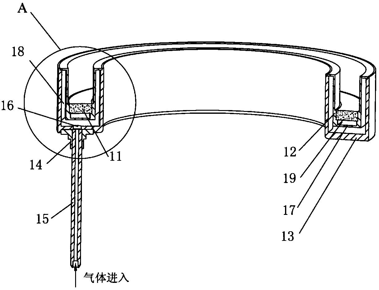
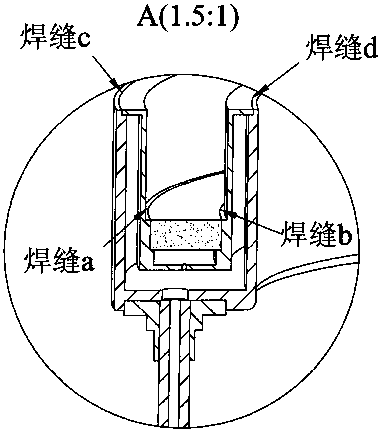
[0039] Such as Figure 2-Figure 4 As shown, the lightweight integrated anode 1 includes an annular porous material plate 11 , an annular side wall 12 , an annular base 13 , an air pipe support 14 , an air pipe 15 , a primary air inlet 16 , and a secondary air inlet 17 . The annular porous material plate 11 is nested in the annular side wall 12, and the outer and inner welds (weld a, b) are welded by electron beam welding to form a secondary distribution cavity 19, which is welded by electron beam A first-level distribution cavity 18 is formed on the ring-shaped base 13 made of stainless steel. The first-level distribution cavity 18 is provided with a first-level air intake hole 16 on the bottom plane, and eight holes with a diameter of 0.2mm are evenly distributed along the circumference on the bottom plane of the annular side wall 12. The secondary air intake hole 17, the secondary air intake hole 17 and the primary air intake hole 16 are staggered to avoid the gas flowing in...

Embodiment 2

[0042] Such as Figure 6-Figure 7As shown, the lightweight integrated anode 1 includes an annular porous material plate 11, an annular inner side wall 12, an annular base 13, an air pipe support 14, an air pipe 15, a primary air intake hole 16, a secondary porous air intake ring 20 and Annular outer wall 21. First, electron beam welding is used to respectively weld the secondary porous intake ring 20 on the annular outer wall 21 (weld e) and the annular inner wall 12 (weld f). Then the annular porous material plate 11 is nested into the U-shaped groove completed by the above welding, and the outer and inner two welds (welds a, b) are welded to form a secondary distribution chamber 19, which is passed through the electron beam The primary distribution cavity 18 is formed on the annular base 13 (welding seam c, d) made of stainless steel by welding, the primary distribution cavity 18 is provided with a primary air intake hole 16 on the bottom plane, and one end of the trachea s...


PUM


Abstract

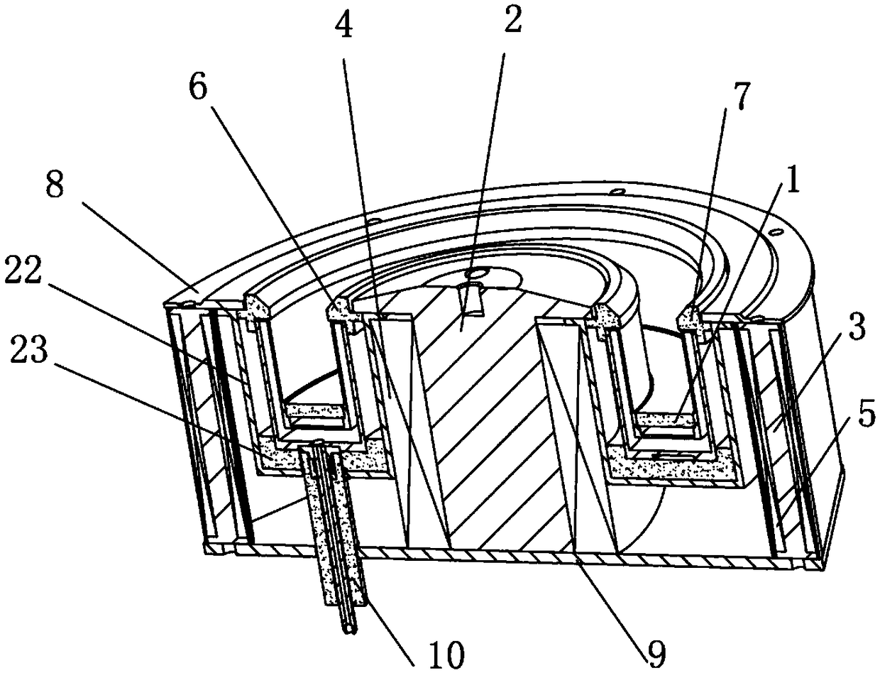
The invention discloses a Hall thruster adopting a lightweight integrated anode. The Hall thruster comprises a bottom plate, wherein an inner magnetic core wound with an inner magnetic coil is configured at the centre of the bottom plate; a plurality of outer magnetic cores wound with outer magnetic coils are configured at the periphery of the bottom plate; the lightweight integrated anode is arranged between the inner magnetic core and the outer magnetic cores; a protective cover is arranged outside the anode; and the protective cover and the anode are insulated and supported by ceramic. An inner ceramic ring and an outer ceramic ring are arranged at the outlet of the lightweight integrated anode, and the inner ceramic ring and the outer ceramic ring are compacted by the outer edge of the inner magnetic core and a front panel separately; and all the parts are installed on the bottom plate, and an insulation sleeve sleeves the gas pipe of the lightweight integrated anode. According to the Hall thruster disclosed by the invention, an integrated anode structure is adopted, and the flowing and distribution characteristics of a gas are improved, so that the thruster is better in ionization effect, better in performance, lower in thermal load, higher in the capacity of resisting to severe mechanical environments, more compact in structure, smaller in size, and lighter in weight.

Description

technical field [0001] The invention relates to a Hall thruster, in particular to a Hall thruster using a lightweight integrated anode. Background technique [0002] Hall thrusters have been widely used in various spacecraft such as satellites and deep space probes. Although the traditional Hall thruster has the advantages of high thrust density, high thrust power ratio and high reliability, it also has a series of problems: [0003] (1) Performance advantages such as specific impulse and efficiency are not obvious; [0004] (2) The volume and weight have reached the limit according to the design idea of ​​the traditional Hall thruster, and there is no room for further optimization; [0005] (3) The ceramic discharge chamber with a large surface-to-volume ratio is used, and the mechanical strength is not high. Therefore, when it is applied to a spacecraft with strict mechanical environment requirements, vibration reduction measures must be considered, thereby increasing th...

Claims


Application Information

Patent Timeline
Patent Type & Authority Patents(China)
IPC IPC(8): F03H1/00
CPCF03H1/0081F03H1/0075
Inventor 赵震刘鹏杭观荣康小录
Owner SHANGHAI INST OF SPACE PROPULSION
Learn More