Hall-effect thruster

a technology of hall effect and thruster, which is applied in the direction of plasma technique, electrical apparatus, plasma use, etc., can solve the problems of limited lifetime resulting from the eroded ceramic of the discharge channel, limiting the lifetime of the thruster, and limiting the operation. the effect of the lifetime, the effect of improving the specific impulse and improving the technical characteristics

Active Publication Date: 2014-04-03
SN DETUDE & DE CONSTR DE MOTEURS DAVIATION S N E C M A
View PDF6 Cites 9 Cited by
  • Summary
  • Abstract
  • Description
  • Claims
  • Application Information

AI Technical Summary

Benefits of technology

[0015]An object of the present invention is to remedy the drawbacks of prior art plasma thrusters, and more particularly to modify Hall effect thrusters or closed electron drift plasma thrusters, in order to improve their technical characteristics, and in particular to improve specific impulse and lengthen lifetime with a significant reduction in the erosion of the discharge channel.

Problems solved by technology

Hall effect thrusters present two major limitations in terms of operation.
A first limitation consists in the limited lifetime resulting from the ceramic of the discharge channel being eroded.
Given their energy, these ions erode the ceramic of the discharge channel, thereby limiting the lifetime of the thruster.
A second limitation lies in the drop in the efficiency of the engine and the acceleration in the aging of the engine at high levels of specific impulse (Isp).
Under such circumstances, the energy of the electrons increases significantly until reaching levels that are incompatible with the ceramic of the channel in the engine.
Nevertheless, this does not make it possible to overcome the problem of the limitation on operation at high voltage.
Bombardment ion thrusters are also known that have grids for accelerating ions and that can operate with levels of specific impulse greater than 4000 s. Nevertheless, the use of grids present certain drawbacks.

Method used


Image

  • Hall-effect thruster
  • Hall-effect thruster
  • Hall-effect thruster

Examples


Embodiment Construction

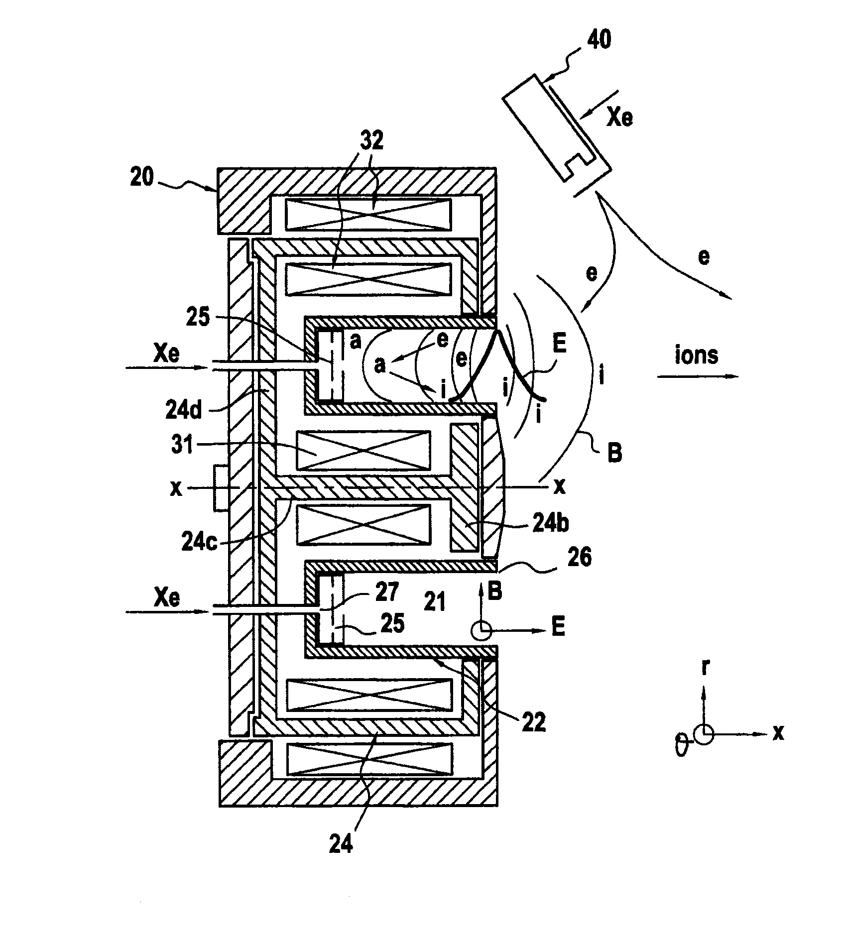
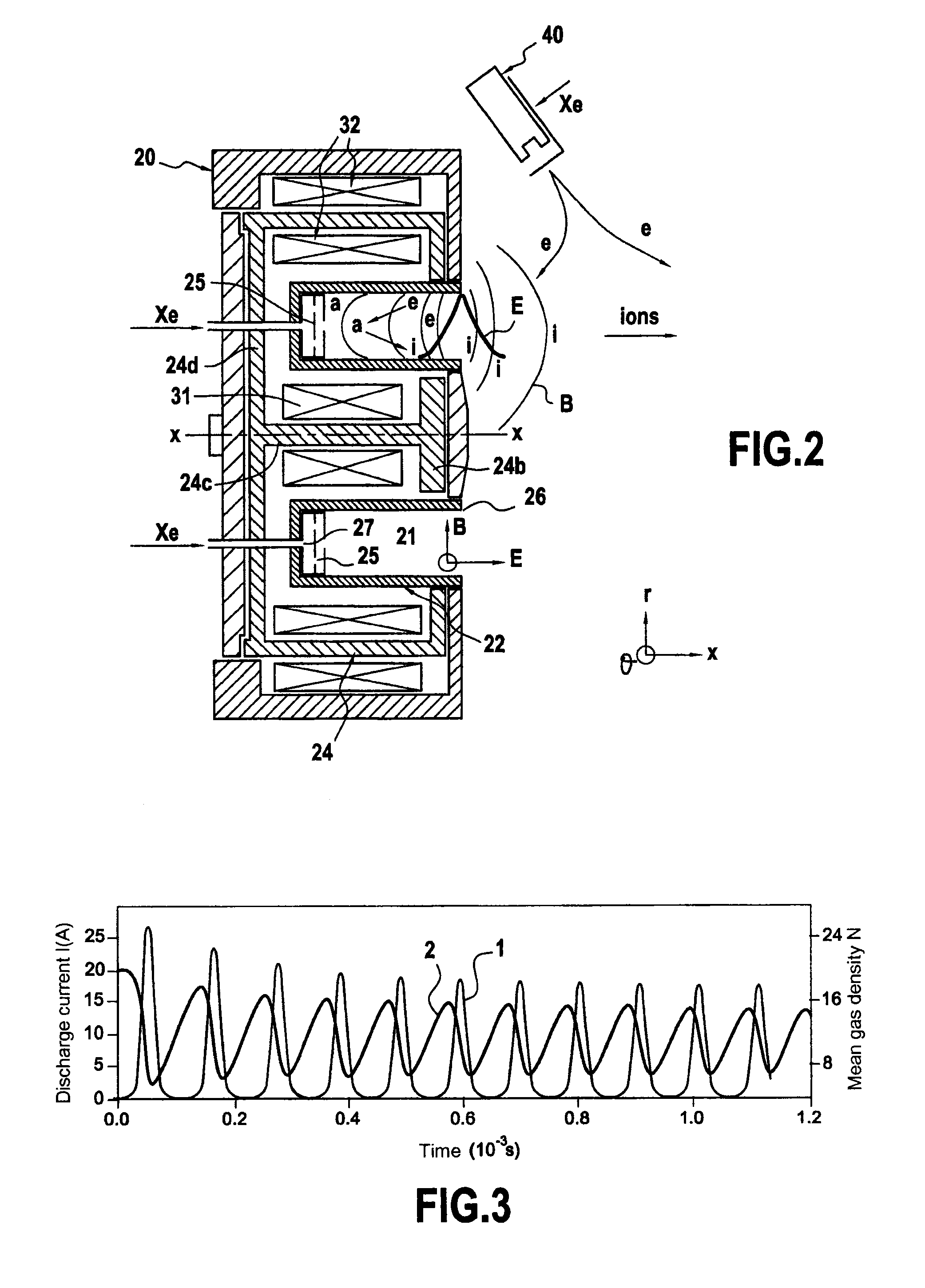
[0028]The invention relates to a Hall effect thruster of general structure as described above with reference to FIG. 2.

[0029]Although often referred to as a “stationary plasma thruster”, the operation of a conventional Hall effect thruster is far from being steady. Several frequency ranges may be considered lying in the range 20 kilohertz (kHz) to several gigahertz.

[0030]At low frequency, a conventional Hall effect thruster is essentially characterized by the following phases:

[0031]a) filling the discharge channel with inert atoms of a propellant such as xenon;

[0032]b) ionizing the inert atoms with energetic electrons in the downstream half of the thruster; and

[0033]c) accelerating and ejecting the ions that have been created by means of the electric field E, which is proportional to the discharge voltage Ud of the thruster.

[0034]The same three-phase cycle is restarted periodically.

[0035]FIG. 3 shows a simplified model of the oscillations in a Hall effect thruster.

[0036]FIG. 3 shows...


PUM


Abstract

A Hall effect thruster includes at least one tank of gas under high pressure, a pressure regulator module, a gas flow rate control device, an ionization channel, a cathode placed in a vicinity of an outlet from the ionization channel, an anode associated with the ionization channel, an electrical power supply unit, an electric filter, coils for creating a magnetic field around the ionization channel, and an additional electrical power supply unit for applying a pulsating voltage between the anode and the cathode.

Description

FIELD OF THE INVENTION[0001]The present invention relates to a Hall effect thruster, also known as a stationary plasma thruster.PRIOR ART[0002]A Hall effect thruster essentially comprises an ionization and discharge channel that is associated with an anode, and a cathode arranged in the vicinity of the outlet from the ionization and discharge channel. The ionization and discharge channel is made of an insulating material such as a ceramic. A magnetic circuit and electromagnetic coils surround the ionization and discharge channel. An inert gas such as xenon is injected into the rear of the discharge channel and into the cathode. The inner gas is ionized in the ionization and discharge channel by colliding with electrons emitted by the cathode. The ions that are produced are accelerated and ejected by the axial electric field created between the anode and the cathode. Within the channel, the magnetic circuit and the electromagnetic coils create a magnetic field that is essentially rad...

Claims


Application Information

Patent Timeline
Patent Type & Authority Applications(United States)
IPC IPC(8): F03H1/00
CPCF03H1/0018F03H1/0075F03H1/0087F03H1/0068F03H1/0062
Inventor ZURBACH, STEPHAN JOSEPHMARCHANDISE, FREDERICOBERG, MICHAEL
Owner SN DETUDE & DE CONSTR DE MOTEURS DAVIATION S N E C M A
Why Eureka
Try Eureka