Fabric snagging analysis device and fabric snagging analysis method
An analysis equipment and snagging technology, which is applied in the direction of material analysis, material analysis through optical means, and optical testing for flaws/defects, etc. It can solve the problems of floating evaluation results, interference evaluation results, and difficulty in reading, etc., to achieve good judgment Efficiency, small interference factors, and the effect of saving equipment costs
- Summary
- Abstract
- Description
- Claims
- Application Information
AI Technical Summary
Problems solved by technology
Method used
Image

Examples
Embodiment approach 1
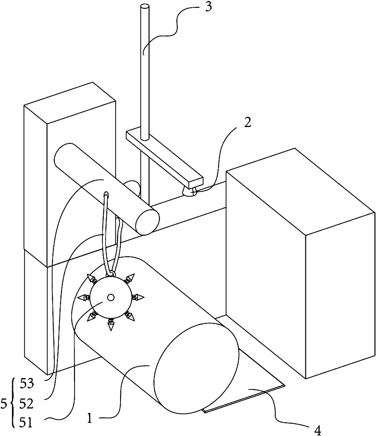
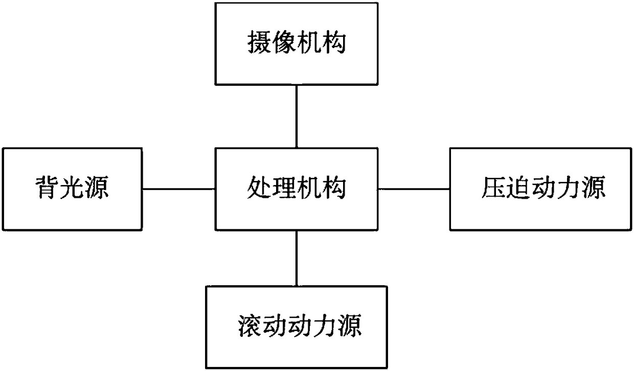
[0046] The first embodiment of the present invention provides a fabric snagging analysis device, see figure 1 and figure 2 As shown in the above, it includes a fabric moving mechanism, a hooking mechanism, a camera mechanism, and a processing mechanism communicating with the camera mechanism, wherein: the fabric moving mechanism includes a roller, the fabric is wound on the roller, and the roller can rotate around its own axis and drive the fabric to rotate. The snagging mechanism can snag the fabric and obtain a snagging surface, and the shooting range of the camera mechanism covers at least one edge of the side of the drum. The camera mechanism sends an image signal to the processing mechanism according to the collected image of the snagging surface on the side edge of the drum; the processing mechanism generates a three-dimensional figure of the snagging surface according to the image signal.
[0047] In this embodiment, the hooking mechanism includes a hooking member pro...
Embodiment approach 2
[0055] The second embodiment of the present invention provides a fabric snagging analysis device. The second embodiment is different from the first embodiment. The main difference is that in the first embodiment of the present invention, the snagging member is Spherical, using the free hanging of the hooking part to hook the thread, which belongs to the improvement made on the basis of the traditional hammer type; and in the second embodiment of the present invention, see image 3 As shown, the guide rail is used to guide the contact snagging between the hooking member and the fabric.
[0056] Specifically, in this embodiment, the thread hooking movement assembly includes a mobile power source, a push block connected to the mobile power source in transmission, and a guide rail for guiding the moving direction of the thread hooking member. The thread hooking piece is installed on the head of the push block, and the push block is arranged on the guide rail. The mobile power sour...
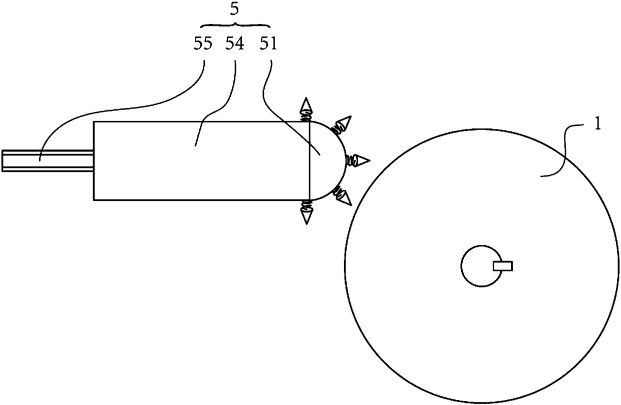
Embodiment approach 3
[0059] The third embodiment of the present invention provides a fabric snagging analysis device, the third embodiment is a further improvement of the second embodiment, the main improvement is that in the third embodiment of the present invention, see Figure 4 As shown, the head of the push block is connected with the tail of the push block through an elastic member. When the hooking piece is in contact with the fabric, the head of the push block protrudes from the guide rail.
[0060] During the hooking process, the head of the push block protruding from the guide rail can bounce under the interaction force between the roller and the hooking piece, thereby preventing the hooking needle from forming a line contact with the fabric surface.
[0061] In this embodiment, a pressure sensor may also be provided at the contact position between the push block and the elastic member, so as to quantitatively obtain the reaction force received by the push block when deformation occurs. ...
PUM
 Abstract
Description
Claims
Application Information
 - R&D Engineer
- R&D Manager
- IP Professional
- Industry Leading Data Capabilities
- Powerful AI technology
- Patent DNA Extraction
Browse by: Latest US Patents, China's latest patents, Technical Efficacy Thesaurus, Application Domain, Technology Topic.
© 2024 PatSnap. All rights reserved.Legal|Privacy policy|Modern Slavery Act Transparency Statement|Sitemap