Supercharge Your Innovation With Domain-Expert AI Agents!

A Design Structure of the Breakthrough Hole for a Chip Resistor in a Power Divider with Wires

A technology of designing structure and giving way holes, applied in circuits, electrical components, waveguide-type devices, etc., can solve the problems of circuit performance degradation, deterioration, discontinuity, etc., to improve the processing yield, reduce deformation problems, and improve processing. The effect of efficiency

Active Publication Date: 2018-11-16
LEIHUA ELECTRONICS TECH RES INST AVIATION IND OF CHINA
View PDF3 Cites 0 Cited by
  • Summary
  • Abstract
  • Description
  • Claims
  • Application Information

AI Technical Summary

Problems solved by technology

However, the lower working tolerance requirements lead to an increase in the matching gap between the relief hole and the resistor cover, resulting in obvious inconsistency and discontinuity in the materials constituting the strip line, which eventually leads to a decline or even deterioration in circuit performance.

Method used


Image

  • A Design Structure of the Breakthrough Hole for a Chip Resistor in a Power Divider with Wires
  • A Design Structure of the Breakthrough Hole for a Chip Resistor in a Power Divider with Wires
  • A Design Structure of the Breakthrough Hole for a Chip Resistor in a Power Divider with Wires

Examples


example 1

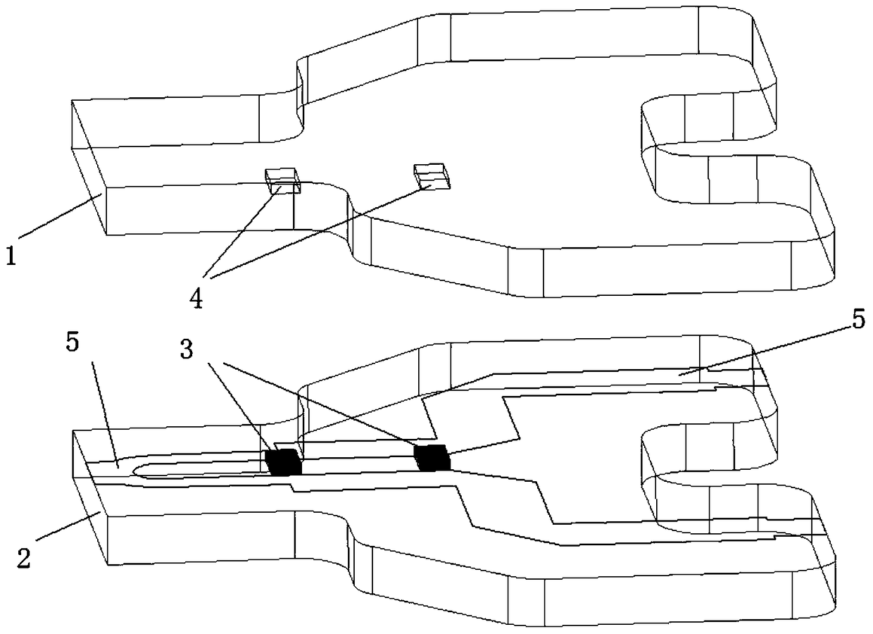
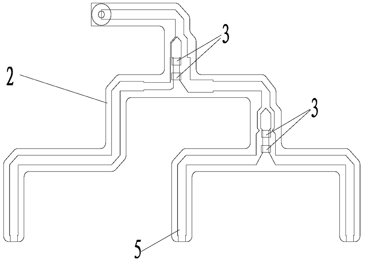
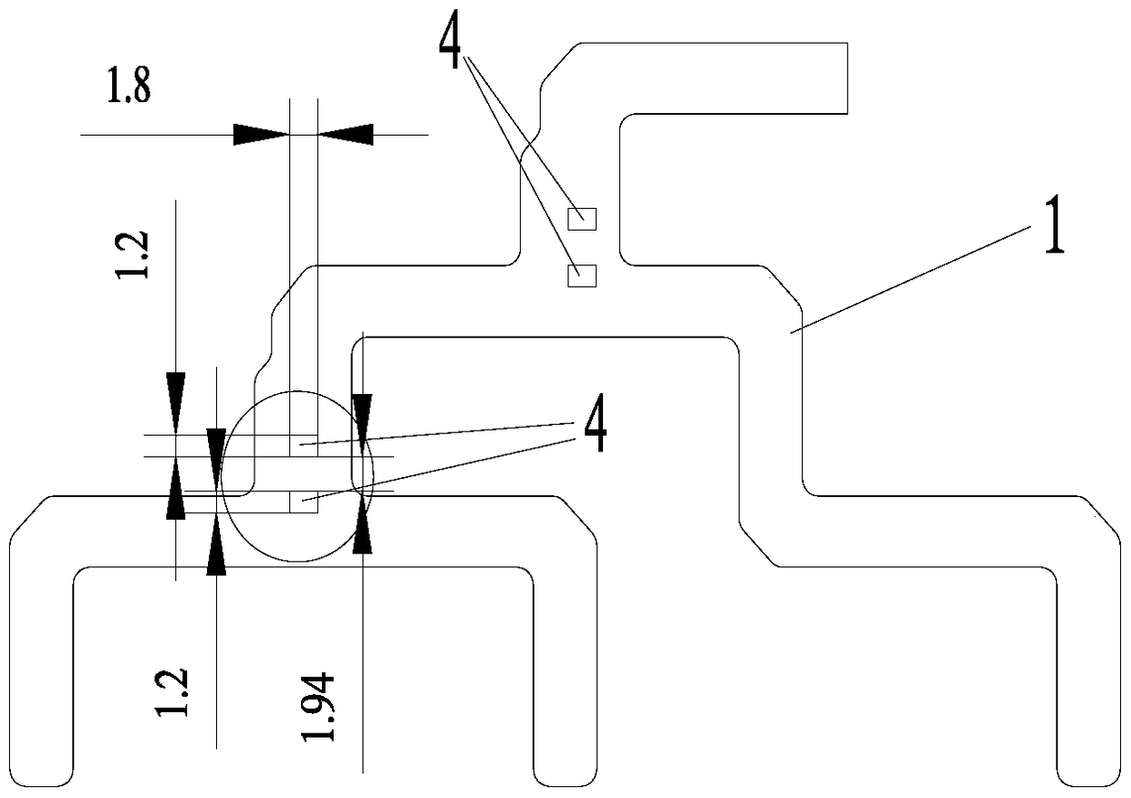
[0044] figure 2 , Figure 4 As an example of the method of the present invention, a single 8mm by 3mm resistor make way hole replaces the original image 3 2 1.8mm by 1.2mm resistors from the old method give way to holes and machined stepped resistor covers in the same area ( Figure 5 , Image 6 ) to match it.

example 2

[0046] Figure 7 , Figure 9 As an example of the method of the present invention, a single 14mm by 3mm resistor make way hole replaces the original Figure 8 4 well-spaced 1.8mm by 1.2mm resistors give way to holes in the old method and machined stepped resistor covers in the same area ( Figure 10 , Figure 11 ) to match it.


PUM


Abstract

The invention belongs to machining and multilayer microwave circuit board assembling, and belongs to the field of microstrip circuit design. In the technical scheme, a rectangular resistor avoidance hole is formed in the area where resistor holes / grooves at the intervals of smaller than 10mm are located on a wired power divider, the length of the rectangular resistor avoidance hole is resistor length plus 1.8mm + / -0.2mm, and the width of the rectangular resistor avoidance hole is resistor width multiplied by the quantity in each group of resistors plus all resistor spacings plus 1mm + / -0.2mm; the resistors are placed in the rectangular resistor avoidance hole; the rectangular resistor avoidance hole is covered with a resistor cover plate, the resistor cover plate is rectangular, the length of the resistor cover plate is the resistor length plus 1.6mm + / -0.2mm, the width of the resistor cover plate is the resistor width multiplied by the quantity in each group of resistors plus all resistor spacings plus 0.8mm + / -0.2mm, the resistor cover plate is thinned relative to the area of the resistors, the thinned thickness is resistor thickness plus 0.1mm + / -0.1mm, and the thinned width is twice of the resistor width.

Description

technical field [0001] The invention belongs to mechanical processing and multi-layer microwave circuit board assembly, and belongs to the field of microstrip circuit design. Background technique [0002] A large number of power dividers are used in electronic equipment systems such as radar and communication as the feed network for signal transmission and distribution, especially in the electronic system of the phased array system. Internal flatness, high isolation between channels, etc. are widely used. [0003] Circuits such as power dividers in the microwave frequency band are generally processed by the printed circuit board process. The circuit pattern (metal) can be guaranteed high accuracy through photography, development, etching and other processes, such as ±0.03mm, but the shape of the circuit board Machining, post-drilling (compared to the need for metallization and other holes have been processed) and other processing errors are large, generally ± 0.1mm. [000...

Claims


Application Information

Patent Timeline
Patent Type & Authority Patents(China)
IPC IPC(8): H01P5/16
Inventor 孔德武鲍卓如沈荣
Owner LEIHUA ELECTRONICS TECH RES INST AVIATION IND OF CHINA
Features
  • R&D
  • Intellectual Property
  • Life Sciences
  • Materials
  • Tech Scout
  • Unparalleled Data Quality
  • Higher Quality Content
  • 60% Fewer Hallucinations
Learn More