Novel workpiece mounting and positioning device

A technology for installing positioning and clamping devices, which is applied in the field of workpiece clamping and can solve problems such as workpiece damage, rising operating costs, and waste of work and operating time.

Inactive Publication Date: 2016-06-15
SHISHI CHUANLANG MACHINERY DESIGN CO LTD
View PDF5 Cites 0 Cited by
  • Summary
  • Abstract
  • Description
  • Claims
  • Application Information

AI Technical Summary

Problems solved by technology

However, the clamping of these workpieces often requires pressing the surface of the workpiece, which easily causes damage to the surface quality of the workpiece
However, some supporting installation methods make it difficult to firmly position the workpiece.
Moreover, in some installation and positioning methods of fastening and clamping, its disassembly is relatively troublesome.
This tends to cause waste of work and operating time in the case of mass operations that require frequent clamping and dismounting of workpieces, thereby prolonging processing time and possibly causing damage to workpieces, and increasing operating costs

Method used


Image

  • Novel workpiece mounting and positioning device

Examples


Embodiment Construction

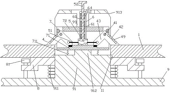
[0007] Combine below figure 1 The present invention will be described in detail.

[0008] A novel workpiece installation and positioning device according to an embodiment of the present invention is used for installing and positioning the workpiece 1, comprising a fixed frame 9, which is installed in the inner cavity of the fixed column 91 of the fixed frame 9 and can be positioned along the The guide rail 99 fixed in the internal cavity slides up and down the movable locking device 7, and the telescopic return spring 711 interposed between the fixed upright 91 and the bottom wall 71 of the movable locking device 7, Wherein, the fixed column 91 is covered with a pressure plate 8 pressed by the pressure positioning spring 911 and guided and limited by the limit column 81, and the movable locking device 7 includes two symmetrically arranged pivots. Each pivot arm 4 is pivotally connected to a respective pivot pin 41 fixed on the shell wall of the movable locking device 7 and is...


PUM


Abstract

A novel workpiece mounting and positioning device is used for mounting and positioning a workpiece (1), and comprises a fixing frame (9), a movable clamping device (7) and a telescopic return spring (711), wherein the movable clamping device (7) is mounted in the inner cavity of a fixedly arranged vertical column (91) of the fixing frame (9) and can slide up and down along a guide rail (99) fixedly arranged in the inner cavity; the telescopic return spring (711) is arranged between the fixedly arranged vertical column (91) and the bottom wall (71) of the movable clamping device (7); a jacking-pressing plate (8) sleeves the fixedly arranged vertical column (91), is jacked and pressed by a jacking-pressing retaining spring (911), and is guided and limited by limited posts (81).

Description

technical field [0001] The invention relates to the field of workpiece clamping, in particular to a novel workpiece mounting and positioning device. Background technique [0002] In the industry, it is usually necessary to perform chucking and positioning for roughly sheet-like workpieces. However, the clamping of these workpieces often requires pressing the surface of the workpiece, which easily causes damage to the surface quality of the workpiece. However, it is difficult to firmly locate the workpiece in some supporting installation methods. Moreover, in some installation and positioning methods of fastening and clamping, its disassembly is relatively troublesome. This is likely to cause waste of work and operation time in the case of mass operations that require frequent clamping and dismounting of workpieces, thereby prolonging the processing time and possibly causing damage to the workpieces, and increasing the operating cost. Contents of the invention [0003] T...

Claims


Application Information

Patent Timeline
Patent Type & Authority Applications(China)
IPC IPC(8): B23Q3/06
CPCB23Q3/067B23Q2240/002
Inventor 范全有
Owner SHISHI CHUANLANG MACHINERY DESIGN CO LTD
Why Eureka
Try Eureka