
A radio frequency array antenna calibration device

An array antenna and calibration device technology, applied in the field of radio frequency simulation, can solve problems such as blurring of distance images, and achieve the effect of solving blurring of ranging

Active Publication Date: 2018-10-16
SHANGHAI INST OF ELECTROMECHANICAL ENG
View PDF5 Cites 0 Cited by
  • Summary
  • Abstract
  • Description
  • Claims
  • Application Information

AI Technical Summary

Problems solved by technology

[0004] In order to solve the problem that the range image is easily blurred in ranging, the present invention aims to provide a radio frequency array antenna calibration device that can improve the ranging speed and accurately determine the wavelength distance

Method used


Image

  • A radio frequency array antenna calibration device
  • A radio frequency array antenna calibration device

Examples


Embodiment Construction

[0015] The present invention will be further described in detail below in conjunction with the accompanying drawings and embodiments. It should be understood that the following examples are only used to illustrate the present invention but not to limit the scope of the present invention.

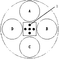
[0016] like figure 1 As shown, the present invention adds a laser distance measuring device to the radio frequency test equipment. The five red dots in the middle of the four receiving antennas, that is, the center area of ​​the test equipment, are the laser emission sources.

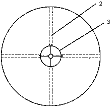
[0017] like figure 2 As shown, in the present invention, a layer of plastic wrap is wrapped on the mouth surface of the radiation antenna, and a film coating that can reflect laser light and transmit radio frequency signals is covered in the central area.

[0018] When performing distance measurement, the laser signal emitted by the laser distance measuring device reaches the thin film coating and is reflected ba...


PUM


Abstract

A radio frequency array antenna calibration device provided by the invention comprises a radiofrequency radiation signal receiving device; the radiofrequency radiation signal receiving device includes a receiving antenna; the antenna calibration device also comprises a standard antenna perpendicular to the calibrated radiation antenna polarization mode; a laser ranging assembly is installed on the radiofrequency radiation signal receiving device; the laser ranging assembly includes a laser emission source, a thin film and a thin film coating capable of reflecting the laser and transmitting radio-frequency signals; the thin film coats the actual surface of the calibrated radiation antenna; and the thin film coating coats the calibrated radiation antenna central zone. The radio frequency array antenna calibration device is able to solve the problem of fuzzy distance measurement in the prior art and achieve the beneficial effects of improved the distance measurement precision and more reliable measurement and debugging results.

Description

technical field [0001] The invention relates to the field of radio frequency simulation, in particular to a radio frequency array antenna calibration device. The main function is to combine laser measurement to assist in improving the mechanical position calibration accuracy of the array antenna from the position, angle and distance. Background technique [0002] As an important simulation platform in the development and verification process of anti-aircraft missiles, the radio frequency guidance control hardware-in-the-loop simulation test system has a degree of confidence that is the most concerned link. The simulation platform must be able to provide reliable and credible information for the development and verification of missiles. The simulation environment can realize the realistic simulation of the whole launching process of the anti-aircraft missile in the laboratory. The radio frequency array antenna system is a very important part of the simulation platform. Its f...

Claims


Application Information

Patent Timeline
Patent Type & Authority Patents(China)
IPC IPC(8): G01S17/08G01C15/00
Inventor 胡敬春刘栗王先腾丁军刘平张宇王立权赵瑜晖
Owner SHANGHAI INST OF ELECTROMECHANICAL ENG
Learn More