A high-friction ship arresting method

A ship and friction technology, applied in the direction of shipping equipment, climate change adaptation, etc., can solve the problems of ship out of control, arrest failure, operation error, etc., achieve low project cost and use cost, ensure effectiveness and reliability, and service life long effect

Active Publication Date: 2017-08-25
NINGBO UNIV
View PDF6 Cites 0 Cited by
  • Summary
  • Abstract
  • Description
  • Claims
  • Application Information

AI Technical Summary

Problems solved by technology

The navigation of the ship will be affected by the weather, currents and the actual working conditions of the ship, but more often it will be affected by human factors, such as misjudgment, operational errors, etc., causing the ship to lose control and deviate from the normal channel to collide with the bridge
At present, the existing direct anti-collision devices cannot meet the requirements of bridge anti-collision in complex situations. Indirect anti-collision facilities generally use floating block anti-collision systems, but the current floating block anti-collision systems are suitable for forward-leaning bow ships. The blocking effect is caused by easy sliding to the bottom of the ship, and whether it is an inland ship or a sea ship, a forward-leaning bow ship is a common ship. Therefore, the current floating block anti-collision system cannot protect the forward-leaning bow ship. Realize effective interception; in addition, the cost of existing anti-collision devices and use costs are high

Method used


Image

  • A high-friction ship arresting method
  • A high-friction ship arresting method
  • A high-friction ship arresting method

Examples


Embodiment 1

[0031] Embodiment 1: As shown in the figure, a high-friction ship arresting method includes the following specific steps:

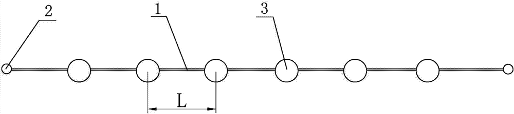
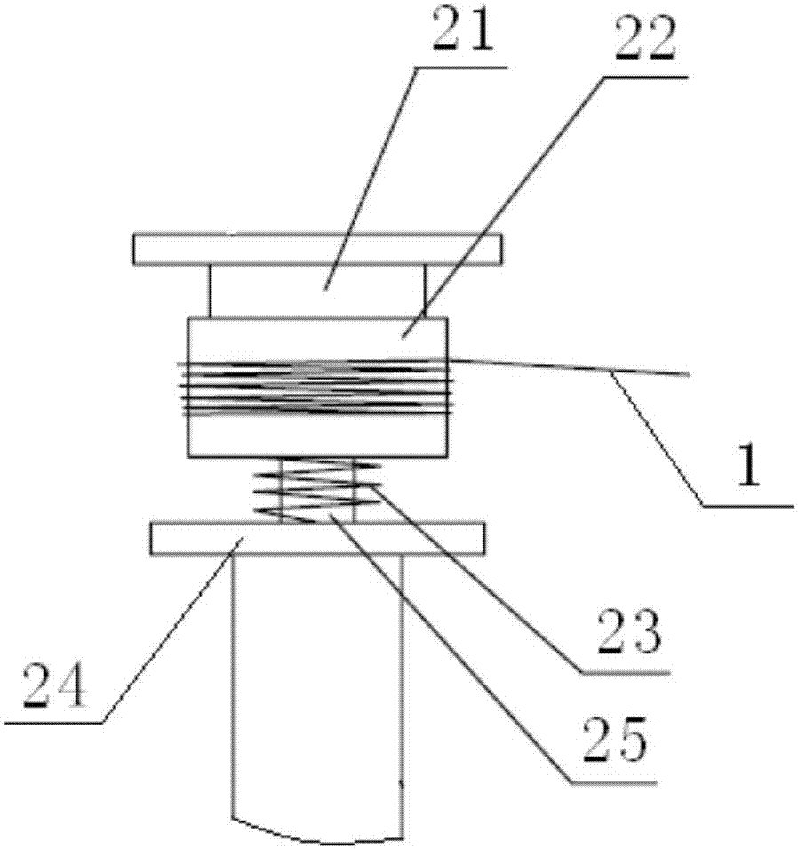
[0032] (1), the two ends of the high-friction interception cable 1 are fixedly connected to the force controller 2 respectively, and the connection form is: force controller 2—high friction interception cable 1—force controller 2, and the force controller 2 The ultimate tensile force of the high-friction interception cable 1 is less than the tensile strength of the high-friction interception cable 1, and the specific structure of the force controller 2 is:

[0033] The force controller 2 comprises a friction block 21, a friction roller 22, a strong spring 23 and a fixed support platform 24, the support platform 24 is fixedly provided with a central shaft 25, the friction block 21 is fixedly arranged on the central shaft 25, and the friction roller 22 and the powerful spring 23 are both sleeved on the central shaft 25, and the powerful spring 23 is connect...

Embodiment 2

[0038] Embodiment 2: As shown in the figure, a high-friction ship arresting method includes the following specific steps:

[0039] (1), the two ends of the high-friction interception cable 1 are fixedly connected to the force controller 2 respectively, and the connection form is: force controller 2—high friction interception cable 1—force controller 2, and the force controller 2 The ultimate tensile force of the high-friction interception cable 1 is less than the tensile strength of the high-friction interception cable 1, and the specific structure of the force controller 2 is:

[0040] The force controller 2 includes a fixed connection platform 26, after the high friction interception cable 1 is bent, it is fixedly connected with a plurality of parallel connection cables 27, and the end of the high friction interception cable 1 is fixedly connected with the connection platform 26;

[0041] (2), fixing a plurality of buoys 3 equally spaced on the high-friction interception cab...

Embodiment 3

[0045] Embodiment 3: As shown in the figure, a high-friction ship arresting method includes the following specific steps:

[0046] (1), the two ends of the high-friction interception cable 1 are fixedly connected to the force controller 2 respectively, and the connection form is: force controller 2—high friction interception cable 1—force controller 2, and the force controller 2 The ultimate tensile force of the high-friction interception cable 1 is less than the tensile strength of the high-friction interception cable 1, and the specific structure of the force controller 2 is:

[0047] The force controller 2 includes a fixed connection platform 26, and the high-friction interception cable 1 is bonded and fixed on the connection platform 26 in a curved shape through an epoxy resin adhesive 28 or other high-strength adhesive;

[0048] (2), fixing a plurality of buoys 3 equally spaced on the high-friction interception cable 1, so that the high-friction interception cable 1 float...


PUM


Abstract

The invention discloses a high-friction-resistance ship arresting method. The high-friction-resistance ship arresting method is characterized in that the two ends of a high-friction-resistance arresting cable or a high-friction-resistance arresting barrier are fixedly connected with a force controller, and the ultimate tension of the force controller on the high-friction-resistance arresting cable or the high-friction-resistance arresting barrier is smaller than the tensile strength of the high-friction-resistance arresting cable or the high-friction-resistance arresting barrier; a plurality of buoys which are distributed at equal intervals are fixed to the high-friction-resistance arresting cable or the high-friction-resistance arresting barrier, so that the high-friction-resistance arresting cable or the high-friction-resistance arresting barrier overall floats on the water and forms a ship arrester; the ship arrester and a ship are controlled to meet a certain relational expression, and when the ship runs into the high-friction-resistance arresting cable or the high-friction-resistance arresting barrier, the ship is effectively arrested through the ship arrester. The high-friction-resistance ship arresting method has the advantages that the situation that arresting is failed due to the fact that the arresting cable or the arresting barrier slides to the bottom of the ship in the process that the ship arrester arrests the ship can be effectively prevented, and accordingly ships in common bow shapes, especially forward bent bow shapes are effectively arrested.

Description

technical field [0001] The invention relates to a method for arresting ships in rivers, in particular to a method for arresting ships with high friction. Background technique [0002] With the rapid development of my country's transportation industry, inland waterway and sea routes are becoming more and more busy, and the tonnage and speed of sailing ships are increasing. On the other hand, there are more and more large bridges across rivers, bays and even straits. The navigation of the ship will be affected by the weather, currents, and the actual working conditions of the ship, but more often it will be affected by human factors, such as misjudgment, operational errors, etc., causing the ship to lose control and deviate from the normal channel to collide with the bridge. At present, the existing direct anti-collision devices cannot meet the requirements of bridge anti-collision in complex situations. Indirect anti-collision facilities generally use floating block anti-coll...

Claims


Application Information

Patent Timeline
Patent Type & Authority Patents(China)
IPC IPC(8): E02B3/26
CPCE02B3/26Y02A30/30
Inventor 杨黎明王硕沈利君郑宇轩王永刚刘军董新龙周风华
Owner NINGBO UNIV
Why Eureka
Try Eureka