Coiled tubing conveying resistance reducing device and using method

A technology of drag reduction device and tubing, which is applied in the direction of drill pipe, casing, earthwork drilling, etc. It can solve the problems of large downhole friction, difficult drilling pressure, difficulty in running in and out, etc., so as to prevent self-locking phenomenon, reduce The effect of small resistance

Active Publication Date: 2022-03-04
XI'AN PETROLEUM UNIVERSITY
View PDF7 Cites 0 Cited by
  • Summary
  • Abstract
  • Description
  • Claims
  • Application Information

AI Technical Summary

Problems solved by technology

However, due to design reasons, most of the existing tractors in China have complex structures and poor reliability, large downhole friction, difficulties in running in and out, and difficult application of drilling pressure.

Method used


Image

  • Coiled tubing conveying resistance reducing device and using method
  • Coiled tubing conveying resistance reducing device and using method
  • Coiled tubing conveying resistance reducing device and using method

Examples


Embodiment Construction

[0050] The present invention will be described in further detail below in conjunction with the accompanying drawings.

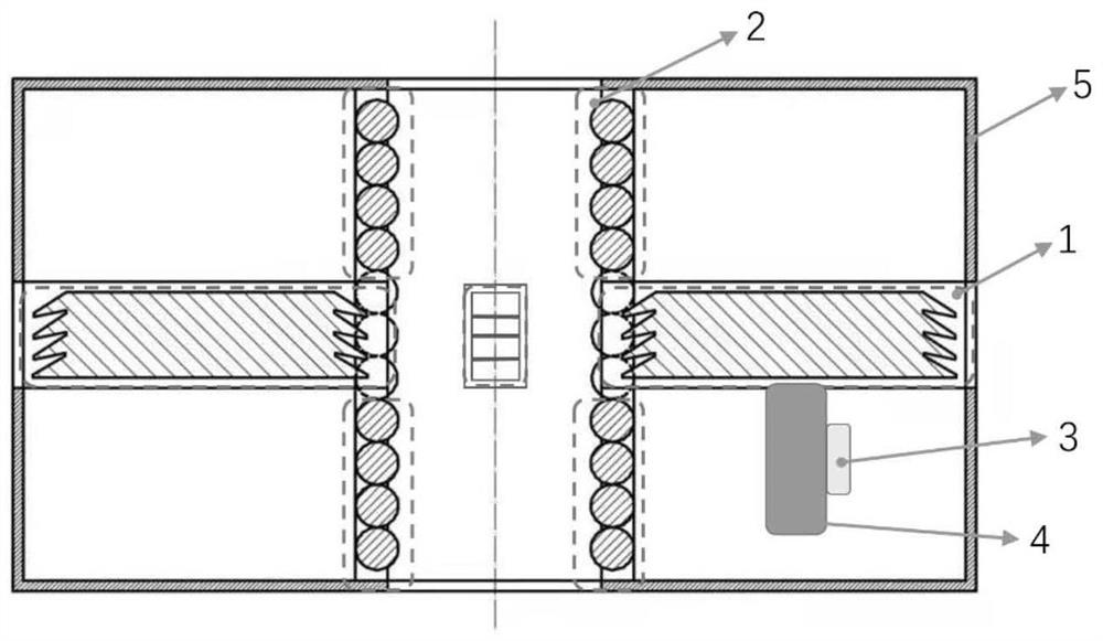
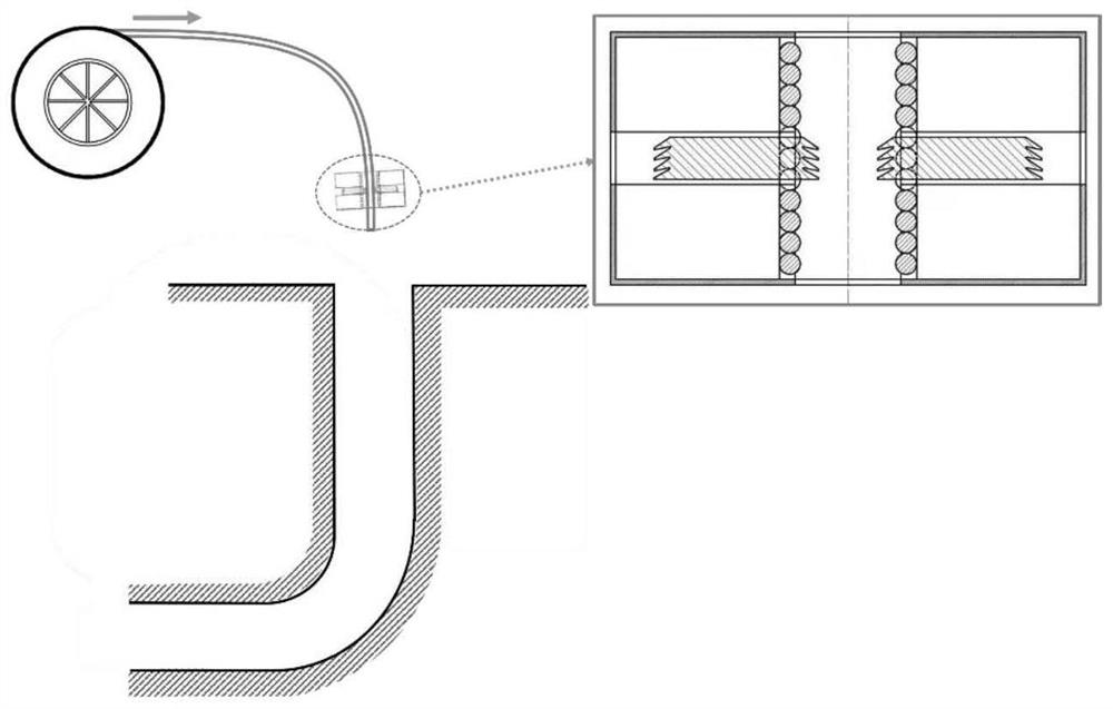
[0051] A drag reduction device for coiled tubing delivery, which is installed in the annular space between the coiled tubing and casing / open hole well wall. During installation, the coiled tubing is lowered into the well and anchored at the wellbore where buckling and self-locking are most likely to occur; in the working state of drag reduction, the coiled tubing can pass through the self-locking point more smoothly by using rolling friction, reducing buckling and self-locking possibility of occurrence. The device can work simultaneously at multiple different buckling self-locking points.

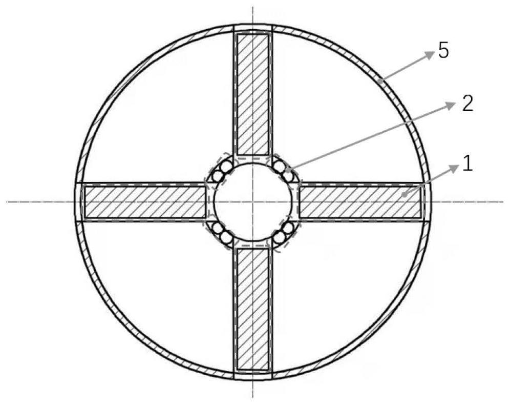
[0052] figure 1 It is a schematic diagram of the main functional modules contained in the present invention. Such as figure 1 As shown, the drag reduction device for coiled tubing transportation includes five functional modules: a limit mechanism 1 , a drag reduction m...


PUM


Abstract

The invention discloses a coiled tubing conveying resistance reduction device and a using method. The coiled tubing conveying resistance reduction device comprises a limiting mechanism, a resistance reduction mechanism, a control mechanism, a power mechanism and a shell. The coiled tubing conveying drag reduction device is installed in an annular space between a coiled tubing and a casing pipe / open hole well wall, the coiled tubing conveying drag reduction device is tripped into a well along with the coiled tubing during installation, the coiled tubing conveying drag reduction device is anchored near a coiled tubing self-locking point position in a drag reduction working state, and the position is obtained through calculation according to a well body structure and related parameters of the used coiled tubing. The device has the advantages of being economical, practical, simple in structure and convenient to operate and maintain.

Description

technical field [0001] The invention belongs to the technical field of coiled tubing downhole tools, and in particular relates to a drag reducing device for coiled tubing transportation and a use method thereof. Background technique [0002] In recent years, during drilling and running of horizontal wells, highly deviated wells, and vertical wells with coiled tubing, the coiled tubing generates and accumulates axial friction, and when the tubing string is lowered into the well, the friction between the coiled tubing and the casing will consume part of the payload at the wellhead, resulting in buckling and self-locking of the coiled tubing, and no penetration after several cycles As a result, the coiled tubing cannot reach the predetermined position, which seriously restricts the construction progress of the coiled tubing site, increases the cost of construction and other downtime, makes it impossible to carry out follow-up operations, and affects the completion of the entire...

Claims


Application Information

Patent Timeline
Patent Type & Authority Applications(China)
IPC IPC(8): E21B17/20E21B23/00
CPCE21B17/20E21B23/00
Inventor 章娅菲钞锐窦益华曹银萍
Owner XI'AN PETROLEUM UNIVERSITY
Why Eureka
Try Eureka