A kind of solar heat collector with changing flow rate of heat collecting tube

A solar collector and collector tube technology, applied in the field of solar energy, can solve the problems of high temperature and shortened service life of the collector tube, and achieve the effects of strengthening heat transfer, avoiding heat loss, and ensuring heat exchange area.

Active Publication Date: 2018-03-20
青岛酒店管理职业技术学院
View PDF3 Cites 0 Cited by
  • Summary
  • Abstract
  • Description
  • Claims
  • Application Information

AI Technical Summary

Problems solved by technology

[0003] In the prior art, a tube-sheet structure is given with the same flow rate in all heat collecting tubes, which causes the temperature of the heat collecting tubes that absorb more heat to be too high, thereby reducing the service life

Method used


Image

  • A kind of solar heat collector with changing flow rate of heat collecting tube
  • A kind of solar heat collector with changing flow rate of heat collecting tube
  • A kind of solar heat collector with changing flow rate of heat collecting tube

Examples


Embodiment Construction

[0028] The specific embodiments of the present invention will be described in detail below in conjunction with the accompanying drawings.

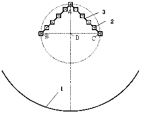
[0029] figure 1 A solar heat collector is shown, the heat collector includes a heat collecting tube 2, a reflector 1 and a heat collecting plate 3, and two adjacent heat collecting tubes 2 are connected through the heat collecting plate 3, so that multiple collectors A tube sheet structure is formed between the heat pipe 2 and the adjacent heat collecting plate 3; the solar heat collector system includes two tube sheet structures, and a certain angle is formed between the two tube sheet structures, and the included angle The direction is opposite to the bending direction of the arc structure of the reflector, and the focal point D of the reflector 1 is located between the angles formed by the tube-sheet structure.

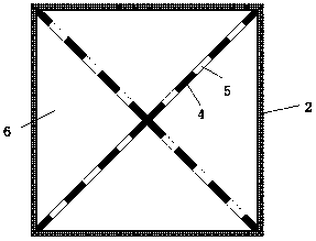
[0030] As an improvement, the cross-section of the heat collecting tube 2 is rectangular, and the heat collecting plate 3 co...


PUM


Abstract

The invention provides a solar thermal collector. The solar thermal collector comprises two tube plate structures, wherein a certain included angle is formed between the two tube plate structures; the direction of the included angle is opposite to the bending direction of an arc structure of a reflecting mirror; the focus of the reflecting mirror is in the included angle formed by the tube plate structures; inner fins are arranged inside collector tubes, are connected with opposite angles of rectangles and divide the interiors of the collector tubes into a plurality of small channels; communication pores are formed in the inner fins; the flows of fluids in different collector tubes are larger and larger in the extension directions from the collection point of the two tube plate structures to the lowest positions at the two sides. The solar thermal collector has the advantages that the uniform mixedness of fluids is maintained, thus avoiding loss of heat during fluid mixing; the temperatures of the collector tubes are ensured to basically keep the same, thus prolonging the overall service lives of the collector tubes.

Description

technical field [0001] The invention belongs to the field of solar energy, in particular to a solar heat collector. Background technique [0002] With the rapid development of modern society and economy, the human demand for energy is increasing. However, the reserves of traditional energy such as coal, oil, and natural gas continue to decrease and become increasingly scarce, resulting in rising prices. At the same time, the environmental pollution caused by conventional fossil fuels is also becoming more and more serious. These greatly limit the development of society and the improvement of human life quality. . Solar thermal conversion is a solar energy utilization method with high energy conversion efficiency and utilization rate and low cost, which can be widely promoted in the whole society. In solar heat utilization devices, the key is to convert solar radiation energy into heat energy, and the device that realizes this conversion is called a solar collector. Howeve...

Claims


Application Information

Patent Timeline
Patent Type & Authority Patents(China)
IPC IPC(8): F24S10/75F24S23/70F24S10/70
CPCF24S10/70F24S10/75F24S23/70F24S80/00F24S2010/71F24S2010/751F24S2080/03Y02E10/44
Inventor 赵炜王昌玉范连雷张志坚
Owner 青岛酒店管理职业技术学院
Why Eureka
Try Eureka