Push-type dual purpose mop

A push and mop technology, applied in the field of cleaning tools, can solve problems such as inconvenience and waste of time, and achieve the effect of facilitating life and overcoming the inconvenience of changing cleaning tools

Inactive Publication Date: 2016-08-03
魏国祯
View PDF7 Cites 0 Cited by
  • Summary
  • Abstract
  • Description
  • Claims
  • Application Information

AI Technical Summary

Problems solved by technology

[0003] The invention proposes a push-type dual-purpose mop, which solves the time-consuming and inconvenient problems of changing cleaning tools in the prior art

Method used


Image

  • Push-type dual purpose mop
  • Push-type dual purpose mop

Examples


Embodiment Construction

[0017] The technical solutions in the embodiments of the present invention will be clearly and completely described below with reference to the accompanying drawings in the embodiments of the present invention. Obviously, the described embodiments are only a part of the embodiments of the present invention, but not all of the embodiments.

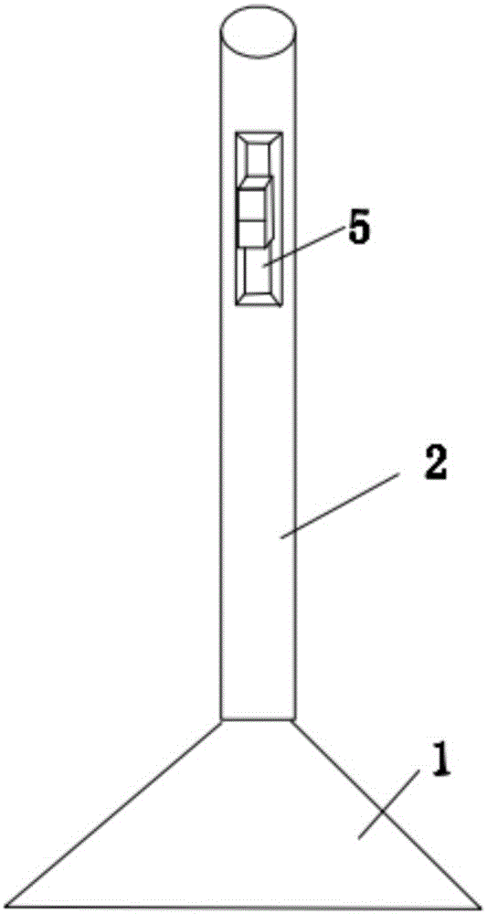
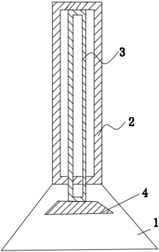
[0018] like figure 1 , figure 2 As shown, the embodiment of the present invention provides a push-type dual-purpose broom, including a broom handle 2 and a broom head 1, as well as a mop 4 and a connecting rod 3, the connecting rod 3 can move inside the broom handle 2, One end of the connecting rod 3 is connected with a sponge 4, and the other end is connected with a switch 5. In order to make full use of the space, the shape of the mop 4 is a rectangle, and the width of the mop 4 is 2 / 3 of the width of the broom head. The length of the mop 4 is 1 / 3 of the length of the broom head.

[0019] Pushing the switch 6 can make the connecting ro...


PUM


Abstract

The invention provides a push-type dual purpose mop. The problems that in the prior art, time is wasted for replacing cleaning tools, and replacing is inconvenient are solved. The push-type dual purpose mop comprises a broom handle, a broom head, a mop body and a connecting rod, the connecting rod can move in the broom handle, one end of the connecting rod is connected with the mop body, and the other end of the connecting rod is connected with a switch; the connecting rod can move inside the broom handle by pushing the switch, the mop body extends out of the broom handle, and the connecting rod can drive the mop body to return back by pushing back the switch. According to the push-type dual purpose mop, a broom and the mop are combined reasonably, the inconvenience of wasting time to replace the cleaning tools is overcome, and the great convenience is brought to life of people.

Description

technical field [0001] The invention relates to the field of cleaning tools, in particular to a push-type dual-purpose mop. Background technique [0002] The broom is a cleaning tool, and it is time-consuming and troublesome to replace the mop after sweeping. SUMMARY OF THE INVENTION [0003] The present invention proposes a push-type dual-purpose mop, which solves the problems of time-wasting and inconvenience in replacing cleaning tools in the prior art. [0004] The technical scheme of the present invention is realized as follows: [0005] A push-type dual-purpose mop includes a broom handle and a broom head, as well as a mop and a connecting rod, the connecting rod can move inside the broom handle, one end of the connecting rod is connected with a mop, and the other end is connected with a mop. The switch is connected, pushing the switch can make the connecting rod move inside the broom handle, extending the mop out of the broom handle, and pushing the switch back, t...

Claims


Application Information

Patent Timeline
Patent Type & Authority Applications(China)
IPC IPC(8): A47L13/12A47L13/42
CPCA47L13/12A47L13/42
Inventor 庄梅兰
Owner 魏国祯
Why Eureka
Try Eureka