Copper casing coil machine

A copper casing and coil machine technology, applied in the direction of heat exchange equipment, etc., can solve the problem of uneven stress on the inner and outer tubes of the casing, uneven deformation of the inner and outer tubes, and poor control of the gap and other problems, to achieve good stable support and transmission effect, convenient adjustment and maintenance, and reduce the labor intensity of personnel

Active Publication Date: 2017-08-15
常熟在路上创业孵化器有限公司
View PDF10 Cites 0 Cited by
  • Summary
  • Abstract
  • Description
  • Claims
  • Application Information

AI Technical Summary

Problems solved by technology

[0003] The metal coil machine in the prior art cannot be directly used to bend the casing, and there are the following problems: when bending, the inner tube of the casing is not in contact with the bending deformation mechanism, resulting in uneven stress on the inner and outer tubes of the casing , resulting in relative sliding, resulting in uneven and non-uniform deformation of the inner tube and the outer tube; the existing metal coil machine can not control the gap between the layers of the spiral layer and the layer of the coil well, and it mostly relies on human intervention and labor. High strength, low efficiency, and large average difference in gap width; copper casing has a large mass per unit volume, and the strength of the coil in the prior art is low, which is prone to deformation, causing the spiral shape of the coil to be deformed, and the coil difficult to remove

Method used


Image

  • Copper casing coil machine
  • Copper casing coil machine
  • Copper casing coil machine

Examples


Embodiment Construction

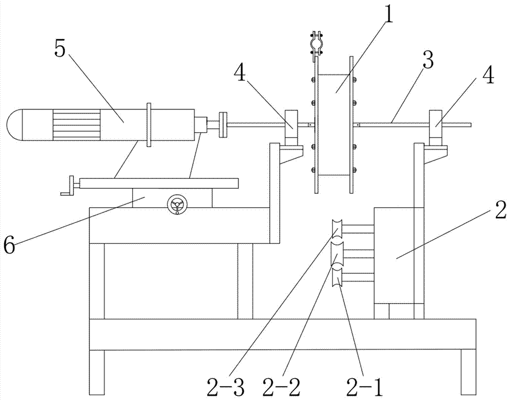
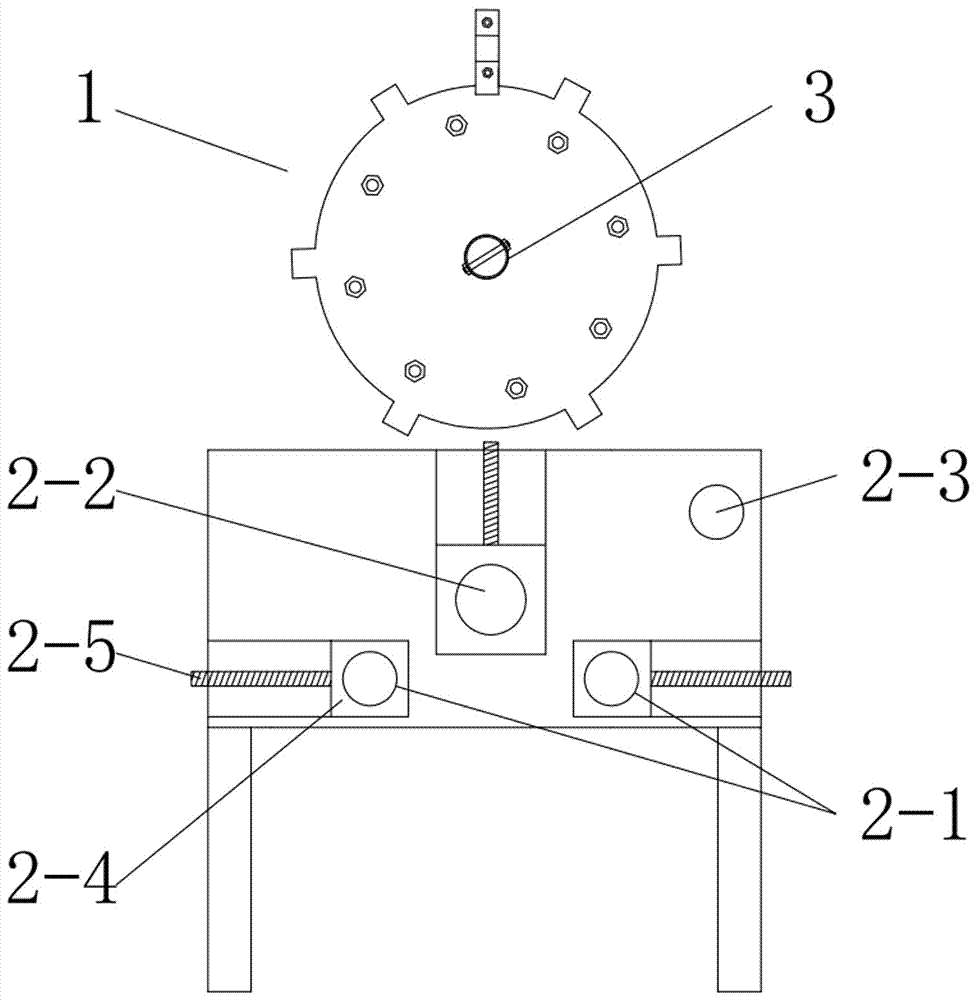
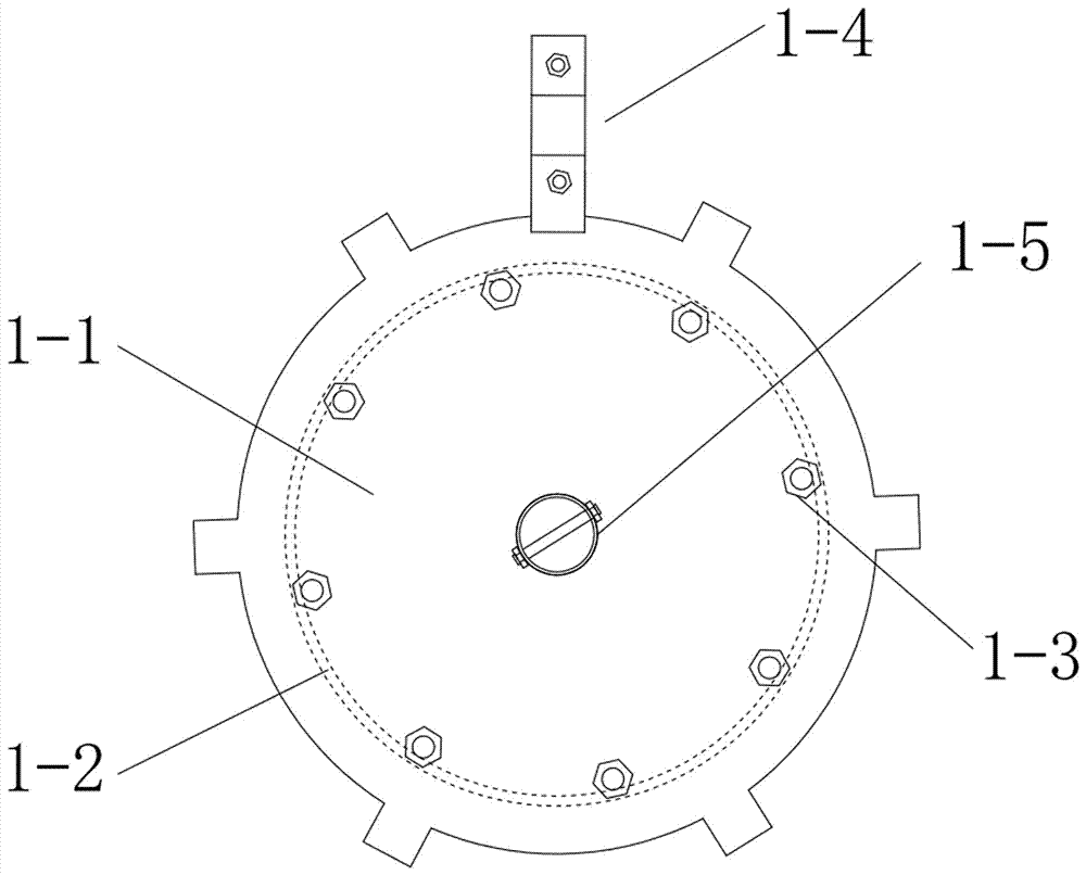
[0035] A copper casing coiler, see figure 1 , including a frame and a bending mechanism 2 arranged on the frame, a coil plate 1, and a pipe head positioning fixture 1-4 is arranged on the coil pipe plate 1, and the pipe head positioning fixture 1-4 is used to place the coiled copper casing The pipe head is fixed on the coil plate 1.

[0036] The coil plate 1 is driven to rotate by the reducer 5 with a motor through the rotating shaft 3. The rotating shaft 3 passes through the bearing and is supported by the bearing seat 4 arranged on the frame. side; the bearing seat 4 is fixed on the long hole of the bearing seat 4 support on the frame by bolts, and the long hole is perpendicular to the axial direction of the rotating shaft 3. The speed reducer 5 is fixed on the sliding table 6 of the frame, and can move along the axial direction of the rotating shaft 3 on the surface of the frame through the sliding table 6 . The slide table 6 is a cross slide table 6, which is equipped wi...


PUM


Abstract

The invention relates to the field of a bending forming processing technology of casing pipe materials, in particular to the field of a preparing technology of a multi-layer spiral-structure copper casing pipe for a heat exchanger. The invention particularly discloses a copper casing pipe coiler. The copper casing pipe coiler comprises a rack, and a bending mechanism and a pipe coiling disc which are arranged on the rack, wherein the pipe coiling disc is driven by a speed reducer with a motor to rotate through a rotating shaft, the rotating shaft penetrates through a bearing and is supported by bearing pedestals arranged on the rack, and the speed reducer is fixed to a sliding table of the rack and can move on the surface of the rack in the axial direction of the rotating shaft through the sliding table; the bending mechanism comprises a dynamic pipe conveying wheel group arranged below the pipe coiling disc, a bending wheel arranged among the dynamic pipe conveying wheel group and a guide wheel which is positioned between the dynamic pipe conveying wheel group and the pipe coiling disc and is close to the periphery of the pipe coiling disc; and a pipe head positioning clamp is arranged on the pipe coiling disc. The copper casing pipe coiler can process the copper casing pipe and make a multi-layer spiral coiled pipe for the heat exchanger and has the advantages of being high in processing efficiency, neat and even in coiled pipe appearance and low in worker labor intensity.

Description

technical field [0001] The invention relates to the technical field of bending and forming processing of sleeve pipes, in particular to the technical field of preparation of copper sleeves with multi-layer spiral structure for heat exchangers. Background technique [0002] The coil is used as a heat exchanger in the carbon dioxide heat pump system. It is made of copper sleeves bent and wound into a multi-layer spiral structure. In order to improve the heat exchange efficiency and save the space of the heat pump unit, the inner and interlayer sleeves of each spiral layer need to be tightly packed. Stacking. At the same time, because the copper sleeve is composed of an inner tube and an outer tube, the mass of the unit volume of the coil is very large. The metal coil machine must use the coil to store and carry the tube body deformed by the bending deformation mechanism. After the coil is completed , remove the coil from the coil pan. [0003] The metal coil machine in the pr...

Claims


Application Information

Patent Timeline
Patent Type & Authority Patents(China)
IPC IPC(8): B21D11/06B21D11/22B21D53/06
CPCB21D11/06B21D11/22B21D53/027B21D53/06
Inventor 张振国戎广林
Owner 常熟在路上创业孵化器有限公司
Why Eureka
Try Eureka