

patellar tendon bandage
A technique for bandages, tendons, used in foot bandages, medical science, non-surgical orthopaedic surgery, etc.
- Summary
- Abstract
- Description
- Claims
- Application Information
AI Technical Summary
Problems solved by technology
Method used
Image

Examples
Embodiment Construction
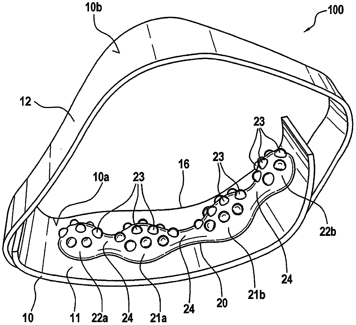
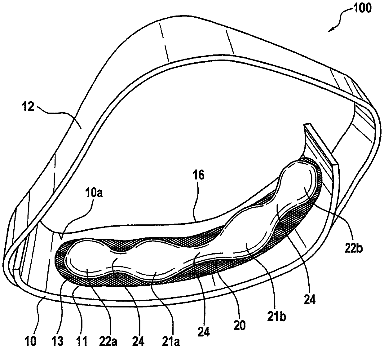
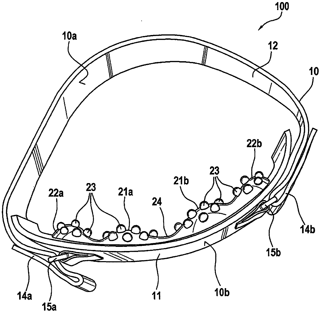
[0049] figure 1 A side view of a preferred embodiment of a patellar tendon bandage (100) according to the present invention is shown. A patellar tendon bandage (100) comprises a bandage component (10) with a functional element (11) and a fixation element in the form of a fixation lace (12). A bandage member (10) has an inner side (10a) and an outer side (10b). The functional element (11) constitutes the front side of the bandage member (10) and is worn under the patella. A recess (16) for the patella is provided in the upper region of the functional element (11). The functional element ( 11 ) can be formed, for example, from a knitted fabric, and the fastening element ( 12 ) can be formed from a knitted or braided fabric.
[0050] A pressure pad (20) is positioned on the inner side (10a) of the functional element (11). The pressure pad comprises: two first pressure pad bodies in the form of pressure pad heads (21a, 21b) with an oval cross section; The second pressure pad ...
PUM
 Abstract
Description
Claims
Application Information