Method of filtering oil through full-band filtering, electrification, separation and adsorption

A full-frequency, oil-filtering technology, applied in the field of hydraulic oil filtration, can solve problems such as different cleanliness requirements, reduced service life of filter elements, and reduced filtration speed, so as to reduce filtering cost and complexity, and suppress filter cake thickness. Increase and improve the effect of filtering performance

Inactive Publication Date: 2016-10-12
王雅莉
View PDF4 Cites 2 Cited by
  • Summary
  • Abstract
  • Description
  • Claims
  • Application Information

AI Technical Summary

Problems solved by technology

[0004] However, the high-pressure filter used in the existing hydraulic system has the following deficiencies: (1) various hydraulic components have different requirements for the cleanliness of the oil, and the particle sizes of the solid particles in the oil are also different. This requires the installation of many different types of filters at different positions in the hydraulic system, which brings about problems of cost and installation complexity; (2) The filter in the hydraulic system mainly adopts the filter cake filter method, and the filtrate is perpendicular to the The surface of the filter element flows, and the intercepted solid particles form a filter cake and gradually thicken, and the filtration speed gradually decreases until the filtrate stops flowing out, which reduces the service life of the filter element

Method used


Image

  • Method of filtering oil through full-band filtering, electrification, separation and adsorption
  • Method of filtering oil through full-band filtering, electrification, separation and adsorption
  • Method of filtering oil through full-band filtering, electrification, separation and adsorption

Examples


Embodiment Construction

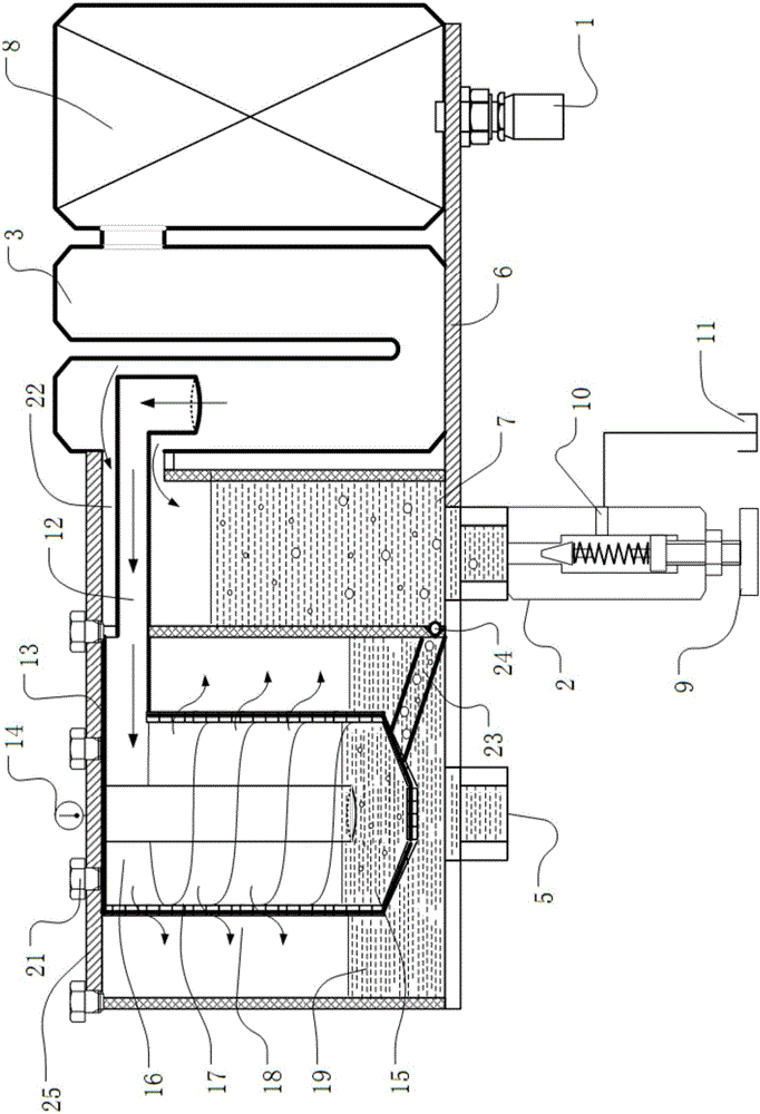
[0044] Please refer to the attached figure 1 to attach Figure 14 As shown, the present invention is an oil filtering method using full-band filtering, electrification, separation and adsorption, which consists of a bottom plate 6, a filter 8, a U-shaped particle separation module 3, an oil return cylinder 7, an inner cylinder 15, a screw Runner 17, filter element 18, outer tub 19 and end cap 25 are composed of several parts. Wherein, the filter 8 , the U-shaped particulate separation module 2 , the oil return cylinder 7 , and the outer barrel 19 are placed on the bottom plate 6 in sequence.

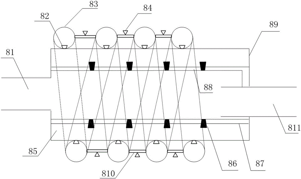
[0045] The filter 8 is used to input the hydraulic oil, and can attenuate the pulsating pressure in the high, medium and low frequency bands in the hydraulic system, and suppress the flow fluctuation. The filter 8 is composed of an input pipe 81 , a casing 89 , an output pipe 811 , a corrugated pipe 83 , an elastic thin wall 87 , and a colloidal damping layer 88 .

[0046] Wherein, th...


PUM


Abstract

The invention relates to a method of filtering oil through full-band filtering, electrification, separation and adsorption. According to the method, the pressure and flow pulsation of hydraulic oil is attenuated by a full-band wave filter; the separation of solid particles is realized by a U-shaped particle separation module, so that the solid particles in oil move toward the wall of a pipe, enter a return oil drum through an air inlet pipe of the return oil drum and then reversely flow to an oil tank, and oil containing trace amount of particles with small particle sizes in the center of a pipeline enters an inner drum through an oil inlet pipe of the inner drum to suffer high-accuracy filtration, thereby prolonging the service life of a filter element; the oil entering the oil inlet pipe of the inner drum flows into a spiral channel of the inner drum in a tangent inflowing manner; the wall of the inner drum serves as a filter element, so that filtrate flows in a manner of clinging to the filter element under the action of centrifugal force, parallels to the surface of the filter element and quickly flow, and the filtered hydraulic oil is vertical to the surface direction of the filter element and outflows to the outer drum; and polluted particles deposited at the bottom of the inner drum can be discharged to the return oil drum timely by an electronic control check valve, thereby prolonging the service life of the filter element.

Description

【Technical field】 [0001] The invention relates to a hydraulic oil filtering method, in particular to an oil filtering method using full frequency band filtering, electrification, separation and adsorption, and belongs to the technical field of hydraulic equipment. 【Background technique】 [0002] Statistics at home and abroad show that about 70% to 85% of hydraulic system failures are caused by oil pollution. Solid particles are the most common and harmful pollutants in oil pollution. Hydraulic system failures caused by solid particle pollutants account for 70% of total pollution failures. Metal debris accounts for 20% to 70% of the particle pollutants in hydraulic system oil. Taking effective measures to filter out the solid particle pollutants in the oil is the key to the pollution control of the hydraulic system, and it is also a reliable guarantee for the safe operation of the system. [0003] Filters are key components of hydraulic systems to remove solid particle con...

Claims


Application Information

Patent Timeline
IPC IPC(8): F15B21/04B03C1/02
CPCB03C1/02F15B21/041
Inventor 王雅莉
Owner 王雅莉
Why Eureka
Try Eureka