Multi-functional nursing bed combined with machinery and air bag

A combined and multi-functional technology, applied in the field of bed, to achieve stable and reliable effect, improve technical level, and use intelligent operation.

Inactive Publication Date: 2016-12-07
冯煤山
View PDF7 Cites 3 Cited by
  • Summary
  • Abstract
  • Description
  • Claims
  • Application Information

AI Technical Summary

Problems solved by technology

None of the current nursing beds can meet the above-mentioned requirements, and the deficiencies, defects and drawbacks of the current nursing beds are obvious

Method used


Image

  • Multi-functional nursing bed combined with machinery and air bag
  • Multi-functional nursing bed combined with machinery and air bag
  • Multi-functional nursing bed combined with machinery and air bag

Examples


specific Embodiment approach 1

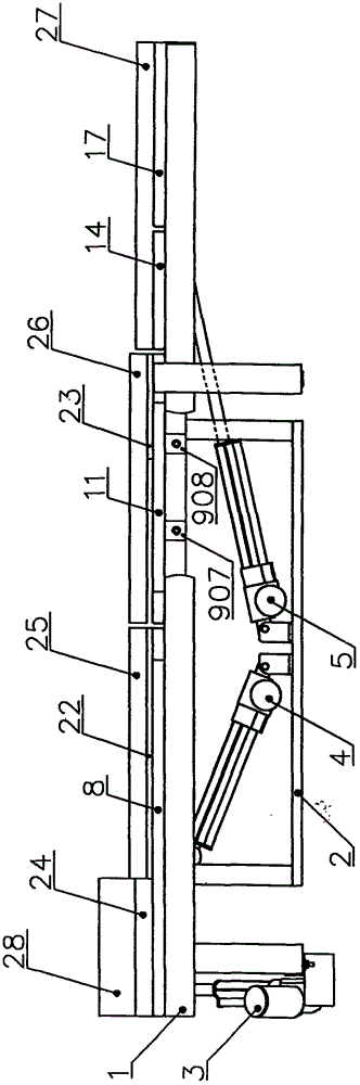
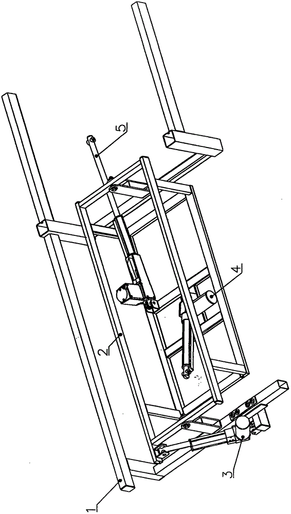
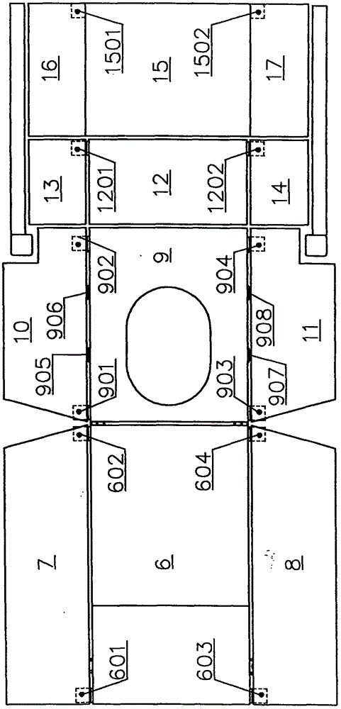
[0052] The present invention will be described in detail below in conjunction with the accompanying drawings. As attached to the manual figure 1 , 2 , 3, 4, and 5 show:

[0053] A multifunctional nursing bed combined with machinery and airbags, consisting of bed frame 1, rocking frame 2, A motor 3, B motor 4, C motor 5, A board 6, B board 7, C board 8, D board 9, E board 10, F board 11, G board 12, H board 13, I board 14, J board 15, K board 16, L board 17, A bag 18, B bag 19, C bag 20, D bag 21, E bag 22. F bag 23, A pad 24, B pad 25, C pad 26, D pad 27, pillow 28, A bracket 601 and B bracket 602 on A board 6, C bracket 603 and D bracket 604, and D board 9 E bracket 901, F bracket 902, G bracket 903, H bracket 904, A piece 905, B piece 906, C piece 907, D piece 908, I bracket 1201 on G board 12, J bracket 1202, J board 15 The composition of K-Torrent 1501 and L-Torture 1502;

[0054] The multifunctional nursing bed combined with the machine and the air bag has a bed fram...

specific Embodiment approach 2

[0062] Implementation is carried out on the basis of the implementation of the first specific embodiment. As attached to the manual figure 1 , 2 , 3, 4, and 5 show:

[0063] The multifunctional nursing bed combined with machinery and airbags has multiple functions and the operation of realizing multiple functions is reflected in:

[0064] (1), the operation of the left body function: start the A motor 3, when the push-pull rod of the A motor 3 shrinks, the rocker frame 2 is pulled, and the rocker frame 2 drives the left side of the D board 9 to move downward and the right side Moving upwards, driven by the D board 9, the left sides of the A board 6, G board 12, and J board 15 move down together with the left side of the D board 9 and the right side simultaneously follows the right side of the D board 9. When the sides move upward together, the human body will turn to the left side; at the same time, the inner sides of B board 7, E board 10, H board 13, and K board 16 will m...


PUM


Abstract

The invention relates to a multi-functional nursing bed combined with machinery and an air bag, pertaining to the technical field of beds. With the machinery and the air bag as the key technology, a bed frame is rotatably and movably connected with a shaking frame through a hinge pin. A bed plate composed of A,B,C,D, E, F,G, H, I, J,K and L plates and movably connected through hinges on adjacent sides is arranged on the bed frame. The bed frame is rotatably and movably connected with the bottom end of an A motor through the hinge pin. The output end of the A motor is rotatably and movably connected with one side of the shaking frame through the hinge pin. The output end of a B motor is rotatably and movably connected with the back side of an A plate through the hinge pin. The output end of a C motor is rotatably and movably connected with the back side of a G plate through the hinge pin. The shaking frame and A, B, C, D parts on the D plate are all fixed. The A plate is fixed with an A bag, a B bag and a C bag. The B plate is fixed with a D airbag. The C plate is fixed with an E bag. The D plate is fixed with an F bag. A mattress composed of A, B, C,D pads is put on the bed plate fixed with A,B, C, D, E, F bags. A pillow is put on the upper end of the A pad for the nursing bed. The multi-functional nursing bed is featured by being ingenious in structure, rich in functions, good in effect and low in cost.

Description

technical field [0001] The invention relates to a multifunctional nursing bed combined with a machine and an air bag, and relates to the technical field of beds. Background technique [0002] As far as the nursing beds used by paralyzed patients are concerned, although there are many kinds, their structures are all different. Because paralyzed patients cannot take care of themselves and lie down for a long time, they are prone to decubitus ulcers. At the same time, they also need to be in a half-sitting state when eating and drinking. Present nursing bed all can not satisfy above-mentioned requirement, and the deficiency, defect and drawback that present nursing bed exist are obvious. Based on the inventor's professional knowledge, rich work experience and unremitting pursuit of business excellence, on the basis of serious and sufficient investigation, understanding, analysis, summary, and research on existing known technologies and current situations, starting from practic...

Claims


Application Information

Patent Timeline
Patent Type & Authority Applications(China)
IPC IPC(8): A61G7/057A61G7/015A61G7/065A61G7/02A61G7/05A61H9/00
CPCA61G7/05776A61G7/001A61G7/015A61G7/02A61G7/05A61G7/05707A61G7/065A61G2203/10A61H9/0078A61H2201/0142A61H2201/0188A61H2201/1207A61H2201/1409A61H2201/1602A61H2201/5023
Inventor 冯煤山
Owner 冯煤山
Why Eureka
Try Eureka