
Loading equipment for material rigidity test and use method thereof

A loading equipment, rigid technology, applied in the direction of analyzing materials, measuring devices, strength characteristics, etc., can solve the problems of complex maintenance work, difficult to obtain point performance at any time, measurement error and other problems

Inactive Publication Date: 2016-12-07
王秀芬
View PDF3 Cites 0 Cited by
  • Summary
  • Abstract
  • Description
  • Claims
  • Application Information

AI Technical Summary

Problems solved by technology

Due to the dynamic nature of load changes and the immediacy of measurement, this method is prone to measurement errors
For equipment with fixed value applied load, due to the discreteness of fixed value, it is difficult to obtain the point performance of expected value at any time
Moreover, slight fluctuations in the load are prone to occur during the hold of a fixed value, resulting in measurement errors
And although some equipment can guarantee the measurement accuracy, the cost is high and the maintenance work is complicated

Method used


Image

  • Loading equipment for material rigidity test and use method thereof
  • Loading equipment for material rigidity test and use method thereof

Examples


Embodiment Construction

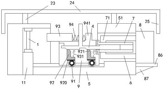
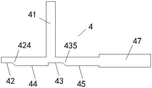
[0009] Combine below Figure 1-2 Embodiments of the present invention will be described in detail.

[0010] The loading device for material rigidity testing according to the embodiment includes a frame 5, a loading trolley 9 capable of moving left and right on the frame 5, and a clamping table fixed at the left end of the frame 5 for clamping the workpiece 1 11, wherein, the right side of the loading trolley 9 is fixedly connected with an externally threaded sleeve 7 for extending into the hollow interior of the rotating shaft 6 and screwing with the internally threaded ring portion 71 at the left end of the rotating shaft 6, the rotating The right end of shaft 6 is power-connected with the output shaft of drive motor 8 installed on the right side of boss 51 of said frame 5, and the bottom of said drive motor 8 is provided with shock-absorbing backing plate 86, and said shock-absorbing pad A reinforcing rib 87 is arranged between the plate 86 and the boss 51, and the shock-ab...


PUM


Abstract

The invention relates to loading equipment for material rigidity test. The loading equipment comprises a machine frame (5), a loading dolly (9) capable of moving on the machine frame (5) leftwards and rightwards and a clamping table (11) fixed at the left end of the machine frame (5) and used for clamping a workpiece (1), wherein an external thread sleeve (7) is fixedly connected to the right side of the loading dolly (9), is used for extending into the hollow inside of a rotating shaft (6) and is in threaded fit with an internal thread ring part (71) at the left end of the rotating shaft (6); the right end of the rotating shaft (6) is in power connection with an output shaft of a drive motor (8) mounted on the right side surface of a boss (51) of the machine frame (5); a damping cushion plate (86) is arranged at the bottom of the drive motor (8); a reinforcing ribbed plate (87) is arranged between the damping cushion plate (86) and the boss (51); the damping cushion plate (86) is used for reducing the vibration force generated when the drive motor (8) runs, so that the running stability of the drive motor (8) is increased.

Description

technical field [0001] The invention relates to the field of material testing equipment, in particular to a loading equipment for testing material rigidity and a method for using the same. Background technique [0002] The rigidity test of the material is an important index for the material performance of the workpiece. Materials may deform differently under different loads and thus exhibit different stiffness properties. Some existing testing equipment continuously applies gradually increasing loads to materials and measures the amount of deformation that occurs during the process. Due to the dynamic nature of load changes and the immediacy of measurement, this method is prone to cause measurement errors. For equipment with fixed value applied load, due to the discreteness of fixed value, it is difficult to obtain the point performance of expected value at any time. Moreover, slight fluctuations in the load are prone to occur during the hold of a fixed value, resulting i...

Claims


Application Information

Patent Timeline
IPC IPC(8): G01N3/02
CPCG01N3/02G01N2203/0032
Inventor 王秀芬
Owner 王秀芬
Learn More