Welding method of electronically controlled grid welding tool

A technology of electronic control and welding tooling, applied in the direction of welding equipment, manufacturing tools, auxiliary devices, etc., can solve the problem that the control function of large current cannot be satisfied

Active Publication Date: 2019-07-02
HUADONG PHOTOELECTRIC TECHN INST OF ANHUI PROVINCE
View PDF9 Cites 0 Cited by
  • Summary
  • Abstract
  • Description
  • Claims
  • Application Information

AI Technical Summary

Problems solved by technology

As the power of traveling wave tubes increases, simply adding a modulation voltage to the anode or focusing electrode is far from being able to satisfy the control function of large currents.

Method used


Image

  • Welding method of electronically controlled grid welding tool
  • Welding method of electronically controlled grid welding tool
  • Welding method of electronically controlled grid welding tool

Examples


Embodiment Construction

[0029] The present invention will be further described below in conjunction with the accompanying drawings. The following examples are only used to illustrate the technical solution of the present invention more clearly, but not to limit the protection scope of the present invention.

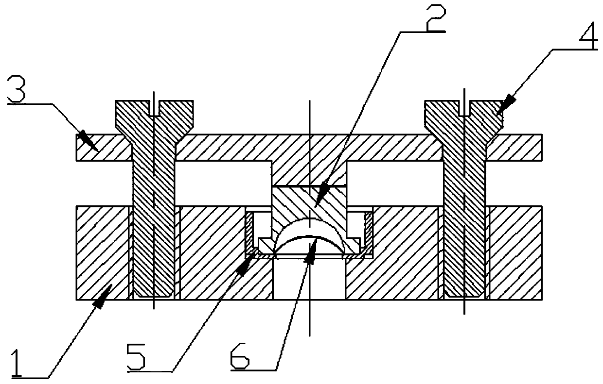
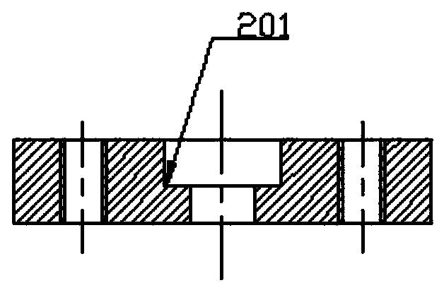
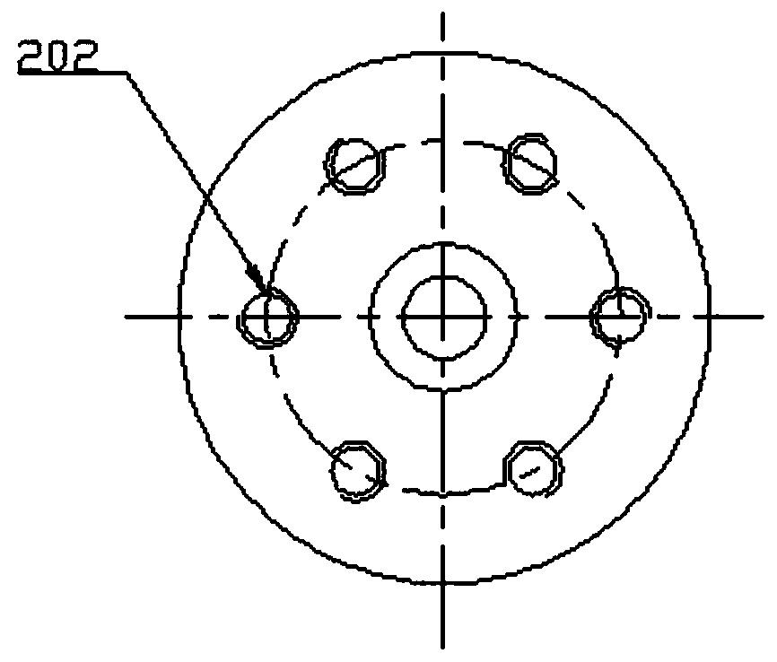
[0030] Such as figure 1 As shown, an electronic control grid welding tooling includes a base 1, a diffusion welding press block 2, a pressing plate 3, a support frame 5, and a control grid 6; figure 2 As shown, the base 1 has a central hole outward from the axis, and the support frame 5 is arranged in the central hole; the bottom wall of the diffusion welding compact 2 is provided with a groove for accommodating the control grid 6, and the diffusion welding compact 2 2 is fixedly arranged on the control grid 6, and the control grid 6 is fixedly arranged on the support frame 5; the pressing plate 3 is fixedly arranged on the diffusion welding pressing block 2.

[0031] The central hole is a st...


PUM

PropertyMeasurementUnit
thicknessaaaaaaaaaa

Abstract

The invention relates to an electronic control aperture plate welding tool and belongs to the technical field of vacuum microwave devices. The welding tool comprises a base, an expansion welding pressing block, a pressing plate, a supporting rack and a control aperture plate. A central hole is formed in the base from the axis to the outside. The supporting rack is arranged in the central hole. A groove used for containing the control aperture plate is formed in the bottom wall of the expansion welding pressing block. The expansion welding pressing block is fixedly arranged on the control aperture plate. The control aperture plate is fixedly arranged on the supporting rack. The pressing plate is fixedly arranged on the expansion welding pressing block. The invention further provides a welding method of the electronic control aperture plate welding tool. For assembling and welding of the control aperture plate in a microwave traveling-wave tube grid-controlled electron gun, the effect that atoms diffuse and infiltrate mutually sufficiently on the contact surfaces between components in the high-temperature vacuum is achieved, and welding between the components is more stable and firmer.

Description

technical field [0001] The invention relates to an electronic control grid welding tool and a welding method, in particular to the assembly and welding of a control grid in a microwave traveling wave tube grid control electron gun, and belongs to the technical field of vacuum microwave devices. Background technique [0002] High-power traveling wave tube is the core device of radar and electronic countermeasure system in modern weapon assembly, and is known as the "heart" of electronic system. As the power of the traveling wave tube increases, simply adding a modulation voltage to the anode or focusing electrode is far from being able to satisfy the control function of large current. Therefore, a control grid electrode closer to the cathode than the anode or focusing electrode is set in the electron gun to control the cathode emission current, so as to achieve the purpose of controlling a large injection current with a small power (or voltage). In the case of pulse work, si...

Claims


Application Information

Patent Timeline
Patent Type & Authority Patents(China)
IPC IPC(8): B23K1/008B23K3/08
CPCB23K1/008B23K3/08
Inventor 王鹏康李金晶苏靖谢智能朱刚
Owner HUADONG PHOTOELECTRIC TECHN INST OF ANHUI PROVINCE
Why Eureka
Try Eureka