Sealing device and mechanical sealing packer

A technology of sealing device and packer, which is applied in sealing/isolation, wellbore/well parts, earthwork drilling and production, etc. It can solve problems such as inability to achieve sealing, small expansion of rubber parts, and failure of downhole casing to deform, etc.

Active Publication Date: 2013-10-02
通化红光石油机械有限责任公司
View PDF15 Cites 0 Cited by
  • Summary
  • Abstract
  • Description
  • Claims
  • Application Information

AI Technical Summary

Problems solved by technology

[0002] At present, the packers used in thermal recovery of heavy oil are composed of steel parts and rubber parts. Since the rubber parts cannot withstand high temperatures above 180 °C, packers can only be used for mining at medium temperatures between 100 °C and 180 °C. Heavy oil; in addition, the wall of the steel part is thin and the expansion of the rubber part is too small (about 1mm-2mm), which often causes the downhole casing to be deformed into a complete circle for some reason to go down to the lower end of the oil well, so that the sealing cannot be achieved. Purpose

Method used


Image

  • Sealing device and mechanical sealing packer
  • Sealing device and mechanical sealing packer
  • Sealing device and mechanical sealing packer

Examples


Embodiment 1

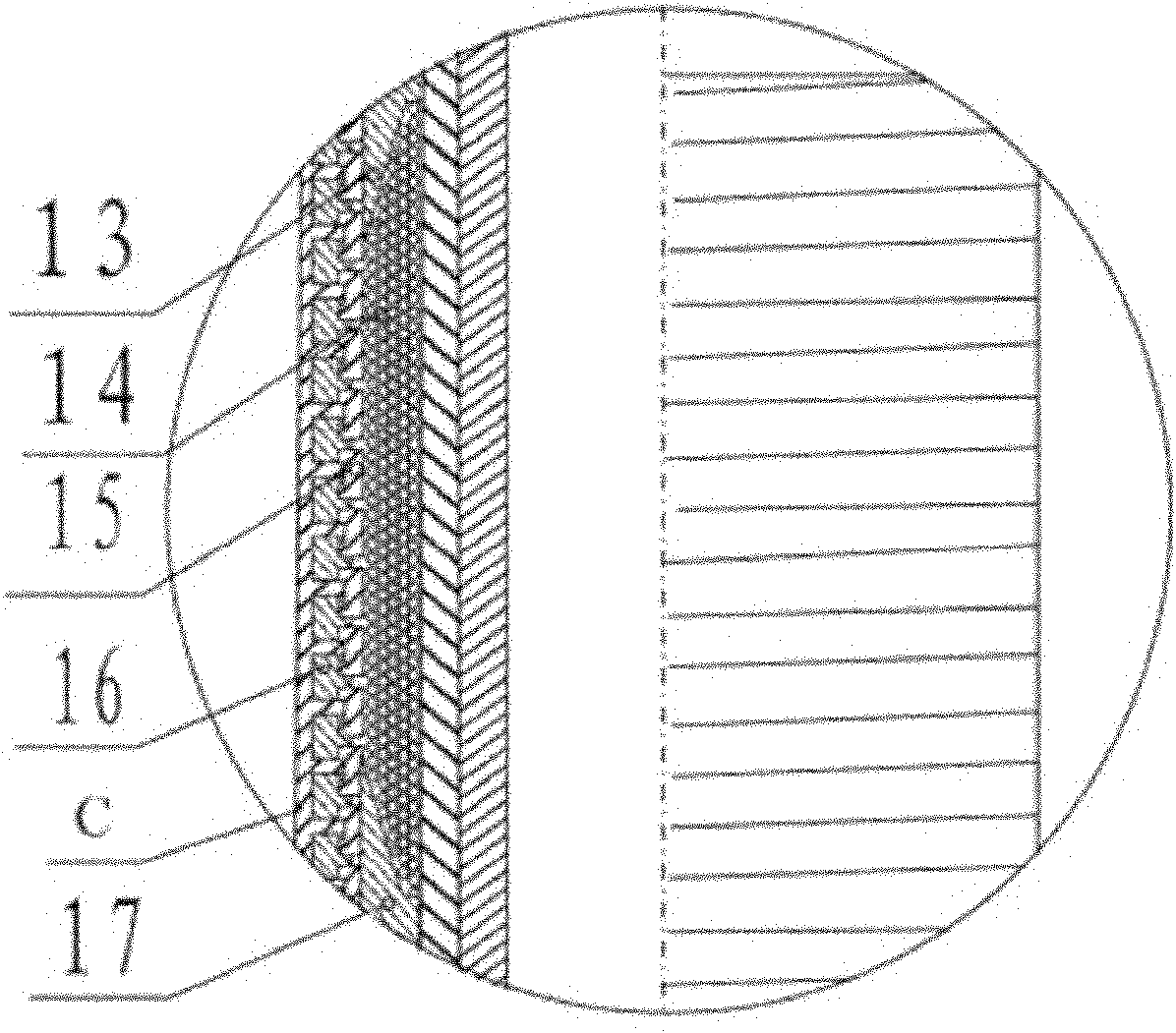
[0030] The sealing device is composed of an upper opening block 13, a ball 14, a bimetallic convex-concave spring 16 and a lower opening block 17. The bimetallic convex-concave spring 16 is composed of red copper C and a convex-concave spring, and the red copper C is laid and welded on the convex-concave spring. On the surface and side, the bimetal convex-concave springs 16 are vertically arranged, and the balls 14 are filled inside the bimetallic convex-concave springs 16. After the balls 14 are filled, the upper and lower surfaces are respectively connected with upper opening blocks 13 and 13 for extruding and sealing the balls 14. Lower opening block 17.

Embodiment 2

[0032] Such as figure 1 As shown, the sealing device is composed of an upper opening block 13, a steel ball 14, a bimetallic convex-concave spring 16, a convex-concave spring bushing 15 and a lower opening block 17, and the bimetallic convex-concave spring 16 is composed of copper C and a convex-concave spring. Copper C is paved and welded on the surface and side of the convex-concave spring, the bimetallic convex-concave spring 16 is arranged vertically, the convex-concave spring bushing 15 and the bimetallic convex-concave spring 16 are nested and fixed, and the steel ball 14 is filled in the outer surface of the convex-concave spring bushing 15 and the bimetallic Inside the cylindrical space formed by the convex-concave spring 16, after the steel ball 14 is filled, its upper and lower surfaces are respectively connected with an upper opening block 13 and a lower opening block 17 for squeezing and closing the steel ball 14, and the upper opening block 13 and the lower opening...

Embodiment 3

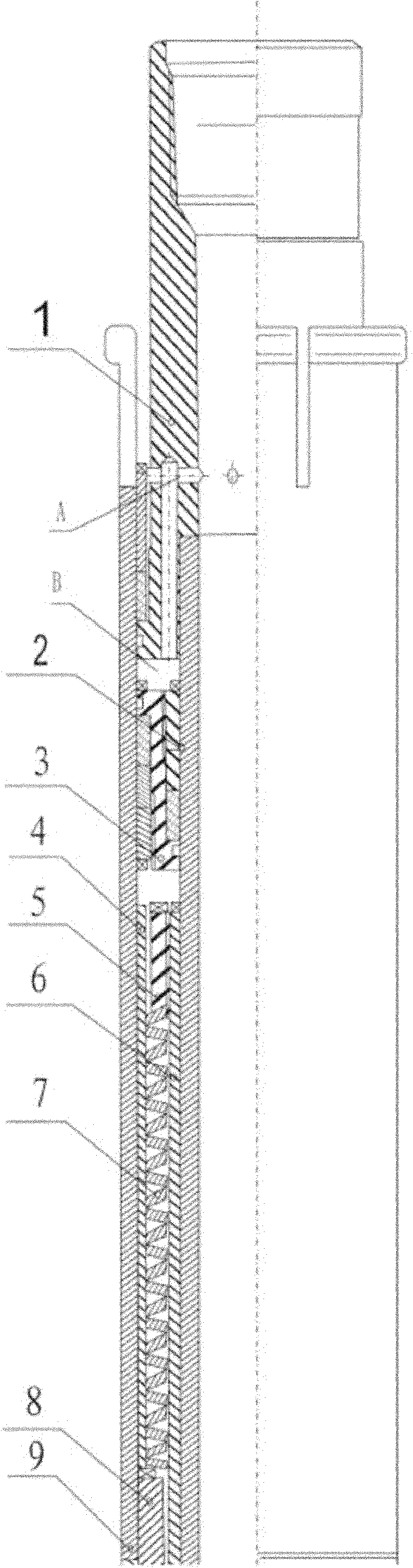
[0037] Such as figure 2As shown, the mechanical seal packer equipped with the above-mentioned sealing device is composed of an upper joint 1, a shear ring 2, a piston 3, a protective sleeve 4, a tension sleeve 5, a tension tube 6, an energy storage spring 7, and an upper connection Cover 8, righting tube 9, thrust sleeve 10, disc spring 11, seat force sleeve 12, sealing device described in embodiment 2, seat force sleeve 18, seat force tube 19, tension screw sleeve 20, spiral tension sleeve 21, Double helix open sleeve 22, key screw 23, lower outer seal group 24, lower connecting sleeve 25, first anti-off screw 26, slip seat 27, slip 28, slip positioning sleeve 29, inner spiral tube 30, center Shaft sleeve 31, lower central shaft tube 32, unsealing screw 33, inner lower seal group 34, lower joint 35 and second anti-off screw 36, the outer layer of the mechanical seal packer is a centralizing tube connected in sequence 9. The seat force tube 19 and the lower connecting sleeve...


PUM


Abstract

The invention provides a sealing device and a mechanical sealing packer, the sealing device comprises an upper open block, a hydraulic medium, a bimetal convex-concave spring and a lower open block, wherein the bimetal convex-concave spring comprises red copper and a convex-concave spring, the red copper is laid and welded on the surface and the side surface of the convex-concave spring, the bimetal convex-concave spring is arranged vertically, the hydraulic medium is placed in the bimetal convex-concave spring, and the upper open block and the lower open block for extruding and closing the hydraulic medium are respectively connected above and below the hydraulic medium; the mechanical sealing packer is provided with the sealing device; and the sealing device and the mechanical sealing packer provided with the sealing device have the characteristics of high temperature resistance and high pressure resistance, and have very important production practical significance in exploitation process of thick oil.

Description

technical field [0001] The invention relates to an oil collection tool, in particular to a sealing device and a mechanical sealing packer. Background technique [0002] At present, the packers used in thermal recovery of heavy oil are composed of steel parts and rubber parts. Since the rubber parts cannot withstand high temperatures above 180 °C, packers can only be used for mining at medium temperatures between 100 °C and 180 °C. Heavy oil; in addition, the wall of the steel part is thin and the expansion of the rubber part is too small (about 1mm-2mm), which often causes the downhole casing to be deformed into a complete circle for some reason to go down to the lower end of the oil well, so that the sealing cannot be achieved. Purpose. Therefore, it is of great practical significance to develop a high-temperature and high-pressure resistant packer that can be used in a high-temperature environment, so as to facilitate the scientific recovery of heavy oil and meet the need...

Claims


Application Information

Patent Timeline
Patent Type & Authority Patents(China)
IPC IPC(8): E21B33/129E21B33/128
Inventor 才景润才永存才艳梅
Owner 通化红光石油机械有限责任公司
Why Eureka
Try Eureka