Measurement circuit and measuring method of LVDT (Linear Variable Differential Transformer)

A technology of measuring circuit and sampling circuit, which is applied in measuring devices, electromagnetic measuring devices, electric/magnetic position measurement, etc., can solve the problems of easy introduction of errors and drift, poor compensation accuracy, poor calibration accuracy, etc., and achieve zero-point residual voltage compensation , Avoid component tolerances and reduce measurement errors

Active Publication Date: 2017-02-01
SUZHOU INST OF BIOMEDICAL ENG & TECH CHINESE ACADEMY OF SCI
View PDF6 Cites 14 Cited by
  • Summary
  • Abstract
  • Description
  • Claims
  • Application Information

AI Technical Summary

Problems solved by technology

However, this type of analog measurement circuit usually has the following disadvantages: 1. The circuit is composed of analog devices, and the parameters of the analog devices are cumbersome to adjust, and it is easy to introduce errors and drifts; 2. When the iron core is at zero, theoretically, the coupling to the secondary The magnetic flux of the primary coil is the same, so the differential signal of the secondary output is zero; in fact, due to the imbalance of the coil, parasitic capacitance, leakage resistance and other reasons, there will be a zero residual voltage; a compensation circuit can be introduced to eliminate the zero residual voltage, At the same time, nonlinear errors will be introduced near the zero point; 3. The demodulation circuit needs the output of the reference oscillation circuit as a reference signal. When the sensor output is in phase with the reference signal, the demodulation circuit can work well, but each link in the signal chain There may be a phase shift, and an analog phase adjustment circuit needs to be introduced to compensate for the phase shift in the signal chain. At the same time, there are also problems of poor compensation accuracy and drift, and the adjustment is cumbersome; 4. The LVDT sensor depends on its structure, and there will be certain nonlinearity. Especially when it is close to the full scale, the output signal has a roll-off, which will affect its effective measurement range; a nonlinear correction circuit needs to be introduced, and in an analog system, there are also problems such as poor correction accuracy, drift, and cumbersome adjustment.

Method used


Image

  • Measurement circuit and measuring method of LVDT (Linear Variable Differential Transformer)
  • Measurement circuit and measuring method of LVDT (Linear Variable Differential Transformer)
  • Measurement circuit and measuring method of LVDT (Linear Variable Differential Transformer)

Examples


Embodiment 1

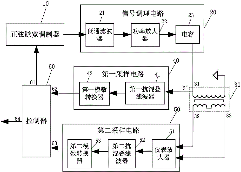
[0049] The present invention provides an LVDT measurement circuit, which includes:

[0050] The sine pulse width modulator 10 is used for outputting a rectangular wave signal with adjustable pulse width and frequency; the pulse width of the rectangular wave signal is adjusted sinusoidally;

[0051] The signal conditioning circuit 20, whose input terminal is connected to the sine pulse width modulator 10, is used to sequentially filter and amplify the rectangular wave signal to output a sine wave signal with adjustable amplitude and frequency;

[0052] Linear differential transformer 30, the primary coil 31 is connected to the signal conditioning circuit output terminal 20 to receive a sine wave signal as an LVDT excitation signal, and the secondary coil 32 outputs an LVDT differential signal;

[0053] The first sampling circuit 40, whose input terminal is connected to the primary coil 31, is used to sample the LVDT excitation signal;

[0054] The second sampling circuit 50, whose input ...

Embodiment 2

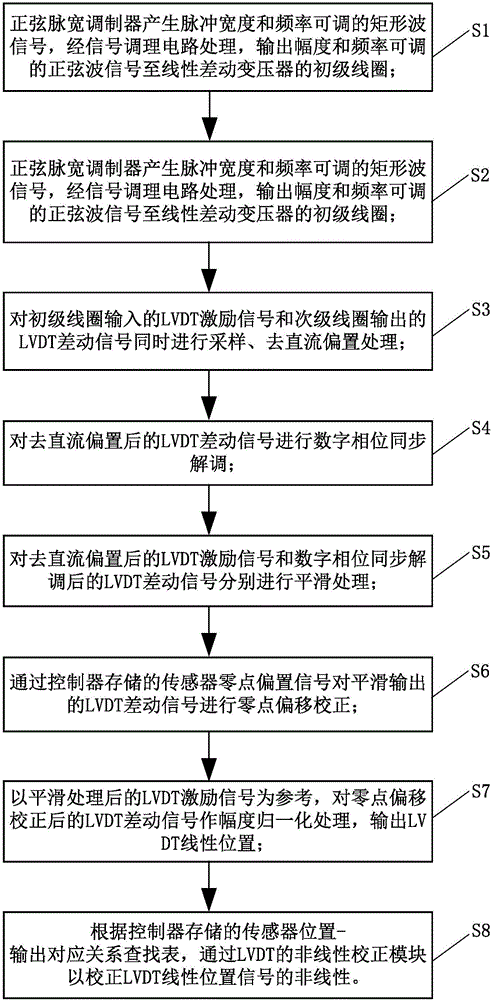
[0064] On the basis of Embodiment 1, this embodiment provides a measurement method based on an LVDT measurement circuit, which includes the following steps:

[0065] S1, a sine pulse width modulator generates a rectangular wave signal with adjustable pulse width and frequency, processed by a signal conditioning circuit, and outputs a sine wave signal with adjustable amplitude and frequency to the primary coil of a linear differential transformer;

[0066] S2, the sine pulse width modulator generates a rectangular wave signal with adjustable pulse width and frequency, processed by the signal conditioning circuit, and outputs a sine wave signal with adjustable amplitude and frequency to the primary coil of the linear differential transformer;

[0067] S3: Simultaneously sample the LVDT excitation signal input by the primary coil and the LVDT differential signal output by the secondary coil and process the DC bias removal;

[0068] S4: Perform digital phase synchronization demodulation on...

Embodiment 3

[0082] On the basis of embodiment 1 and embodiment 2, this embodiment provides specific embodiments of the LVDT measurement circuit and the measurement method thereof.

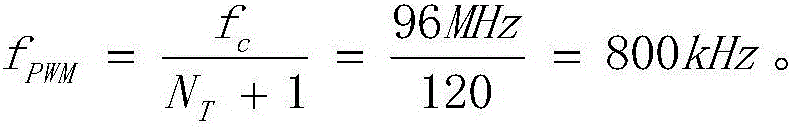
[0083] Taking the MHR500LVDT sensor as an example, the LVDT measurement circuit uses a sine wave excitation frequency of 2.5kHz and an effective value of 3V, and the controller 60 uses the NXP microcontroller LPC1768. The LPC1768 integrates a PWM (Pulse Width Modulation, pulse width modulation) module, which can be used to generate an SPWM (Sinusoidal Pulse Width Modulation, sinusoidal pulse width modulation) signal, which is equivalent to the sinusoidal pulse width modulator 10 of the present invention. The clock frequency of the PWM module is set to 96MHz, and the PWM period register is N T Set to 119, so the frequency f of the PWM signal PWM for:

[0084] f P W M = f c N T + 1 = 96 M H z 120 = 800 k H z .

[0085] Use the general-purpose timer inte...


PUM


Abstract

The invention discloses a measurement circuit of an LVDT (Linear Variable Differential Transformer). The measurement circuit comprises a sinusoidal pulse width modulator, a signal conditioning circuit, a linear variable differential transformer, a first sampling circuit, a second sampling circuit and a controller; the sinusoidal pulse width modulator is used for outputting pulse width and frequency-adjustable rectangular wave signals; the input end of the signal conditioning circuit is connected with the sinusoidal pulse width modulator; the signal conditioning circuit outputs amplitude and frequency adjustable sinusoidal wave signals; the primary coil of the linear differential transformer is connected with the output end of the signal conditioning circuit to receive the sinusoidal wave signals as LVDT excitation signals; the secondary coil of the linear differential transformer outputs LVDT differential signals; the input end of the first sampling circuit is connected with the primary coil; the input end of the second sampling circuit is connected with the secondary coil; and the controller is connected with the output end of the first sampling circuit and the output end of the second sampling circuit and is used for performing amplitude normalization processing to output an LVDT linear position. With the measurement circuit of the LVDT, relatively complicated analog circuit parameter adjustment is avoided, zero-point residual voltage, phase drift and sensor nonlinearity can be effectively compensated. The measurement circuit has the advantages of high stability and can reduce measurement errors.

Description

Technical field [0001] The present invention relates to the technical field of LVDT measurement. More specifically, the present invention relates to an LVDT measurement circuit and a measurement method thereof. Background technique [0002] A linear variable differential transformer (LVDT) is a linear displacement sensor, which is constructed as a differential transformer and includes a barrel-shaped primary coil, two sets of secondary coils, and a nickel-iron alloy iron core. The iron core is a moving part, and its position affects the magnetic field coupling between the primary and secondary windings. The ends of the secondary coils with the same name are connected together, and the output signal is the difference between the signals of the two coils. When the primary coil has an AC excitation signal, the amplitude and phase of the output AC differential signal from the secondary coil reflect the linear position of the iron core. The principle of RVDT (Rotary Variable Differe...

Claims


Application Information

Patent Timeline
Patent Type & Authority Applications(China)
IPC IPC(8): G01B7/00
CPCG01B7/003
Inventor 钱俊孙海旋王弼陡吕丹辉杨维陈奕博梁伟国卢势浩
Owner SUZHOU INST OF BIOMEDICAL ENG & TECH CHINESE ACADEMY OF SCI
Why Eureka
Try Eureka