
Spark discharge constant power arc extinguishing method for intrinsically safe Buck circuit
A spark discharge, intrinsically safe technology, applied in the direction of adjusting electrical variables, control/regulating systems, instruments, etc., can solve problems such as reducing spark energy, achieve the effect of complete circuit structure and ensure safety performance
- Summary
- Abstract
- Description
- Claims
- Application Information
AI Technical Summary
Problems solved by technology
Method used
Image

Examples
Embodiment Construction
[0017] The technical solutions of the present invention will be further described below in conjunction with the accompanying drawings and embodiments.
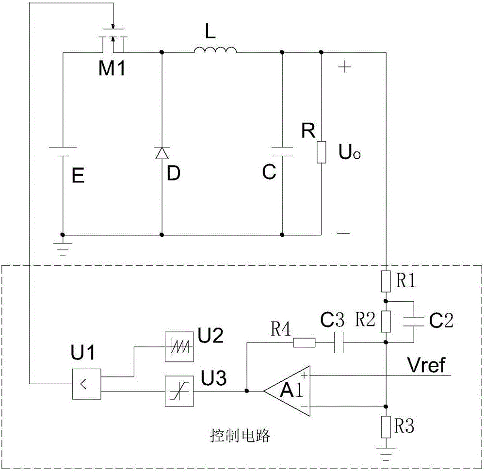
[0018] figure 1 It is a schematic diagram of an existing intrinsically safe Buck circuit with a control circuit. The Buck circuit includes a power supply E, a switching transistor M1, a diode D, an inductor L, a capacitor C and a resistor R; One end of the inductor L is electrically connected to the cathode of the diode D, the other end of the inductor L is electrically connected to one end of the capacitor C, the other end of the capacitor C is electrically connected to the anode of the diode D, and the anode of the diode D is electrically connected to the negative side of the power supply E The terminals are electrically connected, and the resistor R is connected in parallel with the capacitor C. The control circuit includes a resistor R1, a resistor R2, a resistor R3, a resistor R4, a capacitor C2, a capacitor C3, an oper...
PUM
 Abstract
Description
Claims
Application Information