
Limiting structure used for inner part of main body pipeline transportation device of tube push bench

A technology of limit structure and transportation device, which is used in pipeline laying and maintenance, pipes/pipe joints/fittings, machinery and equipment, etc. It can solve the main pipelines that cannot adapt to different sizes, and the main pipelines are prone to rolling and falling off safety accidents. and other problems, to achieve the effect of not easy to shake and fall off, reduce friction, and good stability.

Active Publication Date: 2019-01-11
安徽卓科智能装备有限公司
View PDF5 Cites 0 Cited by
  • Summary
  • Abstract
  • Description
  • Claims
  • Application Information

AI Technical Summary

Problems solved by technology

[0004] The purpose of the present invention is to provide a limit structure for the interior of the main pipeline transportation device of the pipe jacking machine, which can solve the problem that the main pipeline is prone to rolling during transportation, has poor stability, low safety performance, and is easy to fall off and cause safety accidents
And the technical problem that it cannot adapt to the main pipes of different sizes when fixed

Method used


Image

  • Limiting structure used for inner part of main body pipeline transportation device of tube push bench
  • Limiting structure used for inner part of main body pipeline transportation device of tube push bench
  • Limiting structure used for inner part of main body pipeline transportation device of tube push bench

Examples


Embodiment Construction

[0031] The technical solutions of the present invention will be clearly and completely described below in conjunction with the embodiments. Apparently, the described embodiments are only some of the embodiments of the present invention, not all of them. Based on the embodiments of the present invention, all other embodiments obtained by persons of ordinary skill in the art without creative efforts fall within the protection scope of the present invention.

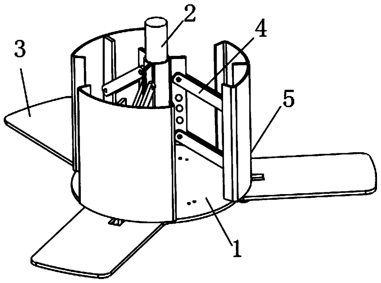
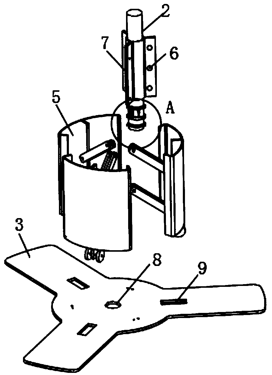
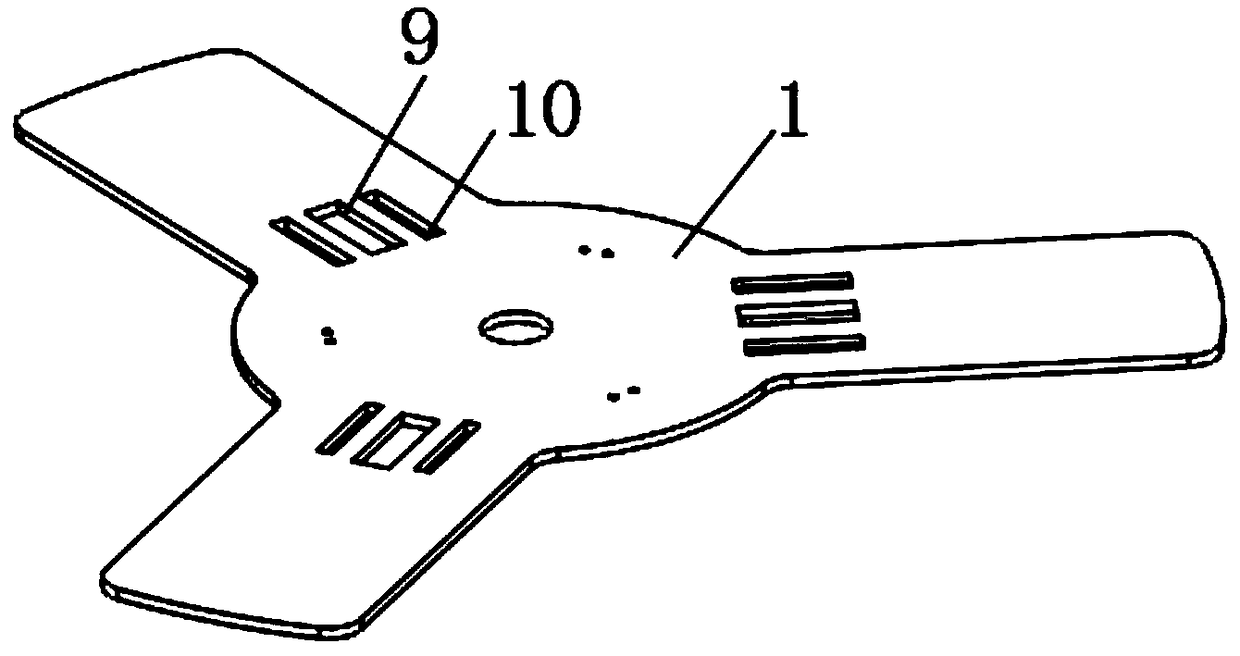
[0032] see Figure 1-7 As shown, a limit structure for the interior of the pipeline transportation device of the main body of the pipe jacking machine, including a circular chassis 1, a connecting plate 3, a vertical rod 2 and a side plate 5, three sets of connecting plates 3 are evenly connected around the chassis 1, and the connecting The middle part of the plate 3 is provided with a through groove 9 along the length direction, the bottom of the connecting plate 3 is provided with sliding grooves 10 on both sides of the t...


PUM


Abstract

The invention discloses a limiting structure used for the inner part of a main body pipeline transportation device of a tube push bench. The limiting structure comprises a circular chassis, connectingplates, a vertical rod and side plates, wherein the periphery of the chassis is uniformly connected with three groups of connecting plates; the middle end of the top of the chassis is connected withthe vertical rod which is longitudinally arranged through a through hole; a plurality of telescopic poles which are longitudinally arranged are uniformly connected between the top of a sleeve ring andthe bottom of a baffle plate; the top of the chassis is uniformly connected with three groups of circular-arc-shaped side plates; and positions, between a roller and the side plates, at the two sidesoutside a mounting plate are transversely connected with positioning rods. The limiting structure is suitable for different working needs, and can be suitable for main body pipelines of different dimensions of the tube push bench, so that the pipelines can be limited by the side plates outside the three side plates; and in use, the main body pipelines are not liable to shake, so that the stable performances are good. Moreover, the main body pipelines can be longitudinally placed and transported, so that the main body pipelines are prevented from rolling in transportation, and therefore, the condition that risk is caused as the main body pipelines drop from the transportation device is avoided.

Description

technical field [0001] The invention relates to a position-limiting structure, in particular to a position-limiting structure used inside a pipeline transportation device of a main body of a pipe jacking machine. Background technique [0002] The pipe jacking machine is a kind of construction machinery specially designed for rock tunnels. It is suitable for various weathered rock soil conditions, and has been more and more widely used in rock tunnel projects such as railways, electric power, water conservancy, coal, mining, transportation, urban underground engineering machines, and subways. Pipe jacking machine is an important equipment for rock tunnel construction. It is mainly used for cutting rock, breaking rock and transporting the broken rock to complete the construction of rock tunnel. The main devices inside the pipe jacking machine are installed inside the hollow main pipeline, and the main pipeline often requires specific devices for transportation. [0003] Howe...

Claims


Application Information

Patent Timeline
IPC IPC(8): F16L1/028F16L1/06
CPCF16L1/028F16L1/06
Inventor 何远浩刘松军徐晓强刘志国童苗苗
Owner 安徽卓科智能装备有限公司
Learn More