
Emergency high-pressure hydraulic control one-way valve

A one-way valve, high-pressure liquid technology, applied in the direction of fluid pressure actuation device, servo motor assembly, mechanical equipment, etc., can solve the problem that the oil cylinder cannot be effectively retracted, and achieve the effect of ensuring safety performance

Pending Publication Date: 2021-08-06
CHINA RAILWAY BAOJI BRIDGE GRP +1
View PDF1 Cites 0 Cited by
  • Summary
  • Abstract
  • Description
  • Claims
  • Application Information

AI Technical Summary

Problems solved by technology

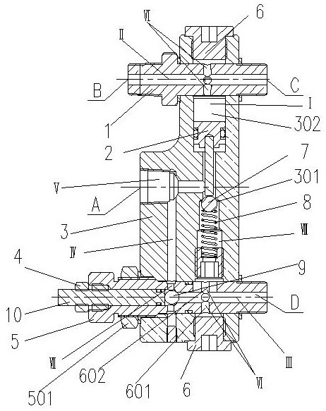
[0004] The technical problem solved by the present invention is to provide an emergency high-pressure hydraulic control check valve, which adopts the method of bolting the return bolt 1 and the emergency bolt 5 with the hydraulic channel to the valve body 3, and adjusts the return stroke and the emergency bolt relative to the valve body 3 The axial staggered position of the hydraulic channel can be adjusted to adjust the diameter of the hydraulic channel, so as to realize the adjustment of the hydraulic flow rate and solve the technical problem of effective control of the hydraulic cylinder's extension and retraction speed; the hydraulic channel of the emergency bolt 5 is used to install the adjusting bolt 10 and the adjusting nut 4 , steel ball Ⅱ9 way to manually cut off or conduct the outflow of hydraulic oil, to solve the technical problem that the oil cylinder cannot be effectively retracted when the pump station or the connecting oil pipeline fails in an emergency state

Method used


Image

  • Emergency high-pressure hydraulic control one-way valve
  • Emergency high-pressure hydraulic control one-way valve

Examples


Embodiment Construction

[0022] Attached below Figure 1-2 Specific examples of the present invention are described.

[0023] The following examples facilitate a better understanding of the present invention, but do not limit the present invention. The following embodiments are only some of the embodiments of the present invention, but not all of them. The components and materials used in the following examples are commercially available unless otherwise specified.

[0024] In the present invention, unless otherwise clearly specified and limited, in the absence of a contrary statement, "upper, lower, left, right, inner, outer, top, bottom, vertical, horizontal" etc. are included in the terms The orientation words only represent the orientation of the term in the normal use state, or for the convenience of describing the present invention and simplifying the description, or the common name understood by those skilled in the art, unless otherwise clearly specified and limited, it should not be regarde...


PUM


Abstract

The invention provides an emergency high-pressure hydraulic control one-way valve. The emergency high-pressure hydraulic control one-way valve is characterized in that the upper part and the lower part of a vertical fluid channel I of a T-shaped fluid channel of a valve body are horizontally bolted with a return bolt and an emergency bolt respectively; the return bolt and the emergency bolt are respectively provided with a water fluid channel II and a water fluid channel III; the fluid channels II and III are communicated with the fluid channel I; the change of the horizontal bolting depth positions of the return bolt and the emergency bolt relative to the valve body is used for adjusting the diameter flow velocity at the joint of the fluid channels II, III and I; a piston assembly is mounted in the fluid channel I; one end of the piston assembly is communicated with the fluid channel II, and the other end of the piston assembly is communicated with the fluid channel III through a steel ball I and a spring in a cutoff or conduction mode; and a manual pressure relief steel ball II and an adjusting bolt are further mounted in the fluid channel III. The emergency high-pressure hydraulic control one-way valve is compact in structure and small in size, and is mainly used for railway hoisting equipment. Hydraulic oil control operation is stable, safe and reliable; a manual emergency release reset function is achieved; an oil cylinder stretching and retracting speed adaptive adjusting function is achieved; mounting and debugging are convenient; and the emergency high-pressure hydraulic control one-way valve is economical, practical and worthy of popularization.

Description

technical field [0001] The invention belongs to the technical field of fluid valves, and in particular relates to an emergency high-pressure hydraulic control check valve. Background technique [0002] Ordinary check valves have the function of one-way conduction, one direction conduction, and the other direction cut-off. Compared with ordinary check valves, the hydraulic control check valve can be opened by hydraulic oil pressure. If there is no hydraulic control pressure, the hydraulic control check valve can only conduct in one direction; when there is hydraulic control pressure, the hydraulic control check valve Conduction to the valve in both directions. [0003] In the prior art, a hydraulically controlled valve that realizes two-way conduction is taken as an example of a dual hydraulically controlled one-way valve disclosed by the authorized announcement number CN206346977U. Although it realizes the miniaturized design of the double hydraulic control check valve, wh...

Claims


Application Information

Patent Timeline
IPC IPC(8): F15B13/02
CPCF15B13/027
Inventor 王路王玉龙梁承庠苏杰张晓军
Owner CHINA RAILWAY BAOJI BRIDGE GRP
Learn More