
Rotary positioning device

A positioning device and positioning piece technology, applied in workpiece clamping devices, manufacturing tools, etc., can solve the problems of reduced work efficiency, easy falling of the plug, frequent plugging and unplugging, etc., to achieve the effect of improving work efficiency and avoiding easy loss.

Inactive Publication Date: 2018-05-04
ANHUI JIANGHUAI AUTOMOBILE GRP CORP LTD
View PDF5 Cites 0 Cited by
  • Summary
  • Abstract
  • Description
  • Claims
  • Application Information

AI Technical Summary

Problems solved by technology

[0003] However, the positioning method in the prior art has certain limitations. The reason is that the pin is an independent part, which is easy to lose during use, and when the entire equipment or tooling needs to be turned over, the pin is easy to fall and is prone to danger. , and frequent plugging and unplugging seriously reduces work efficiency and affects production beats

Method used


Image

  • Rotary positioning device
  • Rotary positioning device

Examples


Embodiment Construction

[0025] Embodiments of the present invention are described in detail below, examples of which are shown in the drawings, wherein the same or similar reference numerals designate the same or similar elements or elements having the same or similar functions throughout. The embodiments described below by referring to the figures are exemplary only for explaining the present invention and should not be construed as limiting the present invention.

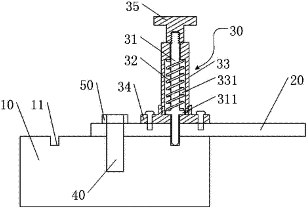
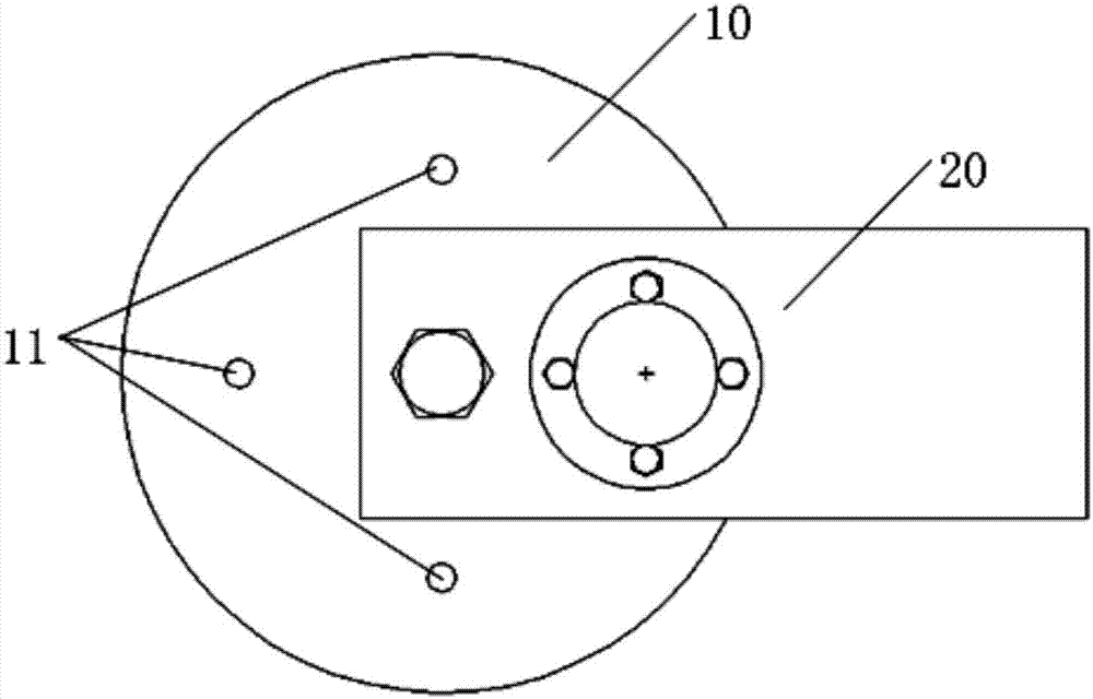
[0026] figure 1 It is the front view of the rotation positioning device provided by the embodiment of the present invention, figure 2 The top view of the rotary positioning device provided for the embodiment of the present invention, such as figure 1 with figure 2 As shown, the rotary positioning device provided by the embodiment of the present invention includes a base 10 , a rotating member 20 and a positioning assembly 30 , and the positioning assembly 30 includes a positioning member 31 .

[0027] Among them, the base 10 is prov...


PUM


Abstract

The invention discloses a rotary positioning device. The rotary positioning device comprises a base, a rotating piece and a positioning module; and the positioning module includes a positioning piece. Multiple positioning holes are formed in the base; one end of the rotating piece is rotationally connected with the base; the positioning piece is movably connected with the rotating piece, and can move up and down along the longitudinal axis of the rotating piece; and the lower end of the positioning piece can be matched with the positioning holes for positioning. When the rotary positioning device is used, as the positioning piece, the rotating piece and the base have a relative connecting relation as a whole, the condition of easiness in bolt loss is prevented; and when the positioning is needed in different positions, the rotating piece only needs to rotate, and the positioning piece can be positioned with the positioning holes in different positions on the base, so that the working efficiency is improved.

Description

technical field [0001] The invention relates to the technical field of positioning on production equipment, in particular to a rotary positioning device. Background technique [0002] On the production equipment or fixtures in the workshop, some parts often need to be rotated or moved to meet the production needs of different working conditions or different workpieces. At this time, it is necessary to locate these rotating or moving parts. The existing positioning The method is to use the pin for positioning. When the position needs to be changed, the pin is pulled out, and the pin is installed at another position. The pin, the workpiece, and the equipment tooling are all independent parts and need to be stored separately. [0003] However, the positioning method in the prior art has certain limitations. The reason is that the pin is an independent part, which is easy to lose during use, and when the entire equipment or tooling needs to be turned over, the pin is easy to fal...

Claims


Application Information

Patent Timeline
Patent Type & Authority Patents(China)
IPC IPC(8): B25B11/00
CPCB25B11/00
Inventor 董培胜
Owner ANHUI JIANGHUAI AUTOMOBILE GRP CORP LTD
Learn More