A charging control method and device

A charging control method and a technology to be charged, which are applied to circuit devices, battery circuit devices, secondary battery charging/discharging, etc., and can solve problems such as slow charging speed, serious heat generation, and low step-down conversion efficiency

Active Publication Date: 2018-06-01
MEIZU TECH CO LTD
View PDF3 Cites 0 Cited by
  • Summary
  • Abstract
  • Description
  • Claims
  • Application Information

AI Technical Summary

Problems solved by technology

[0005] The embodiment of the present invention provides a charging control method and device, which are used to solve the problems of low step-down conversion efficiency, slow charging speed and serious heat generation in the existing charging control method.

Method used


Image

  • A charging control method and device
  • A charging control method and device
  • A charging control method and device

Examples


Embodiment 1

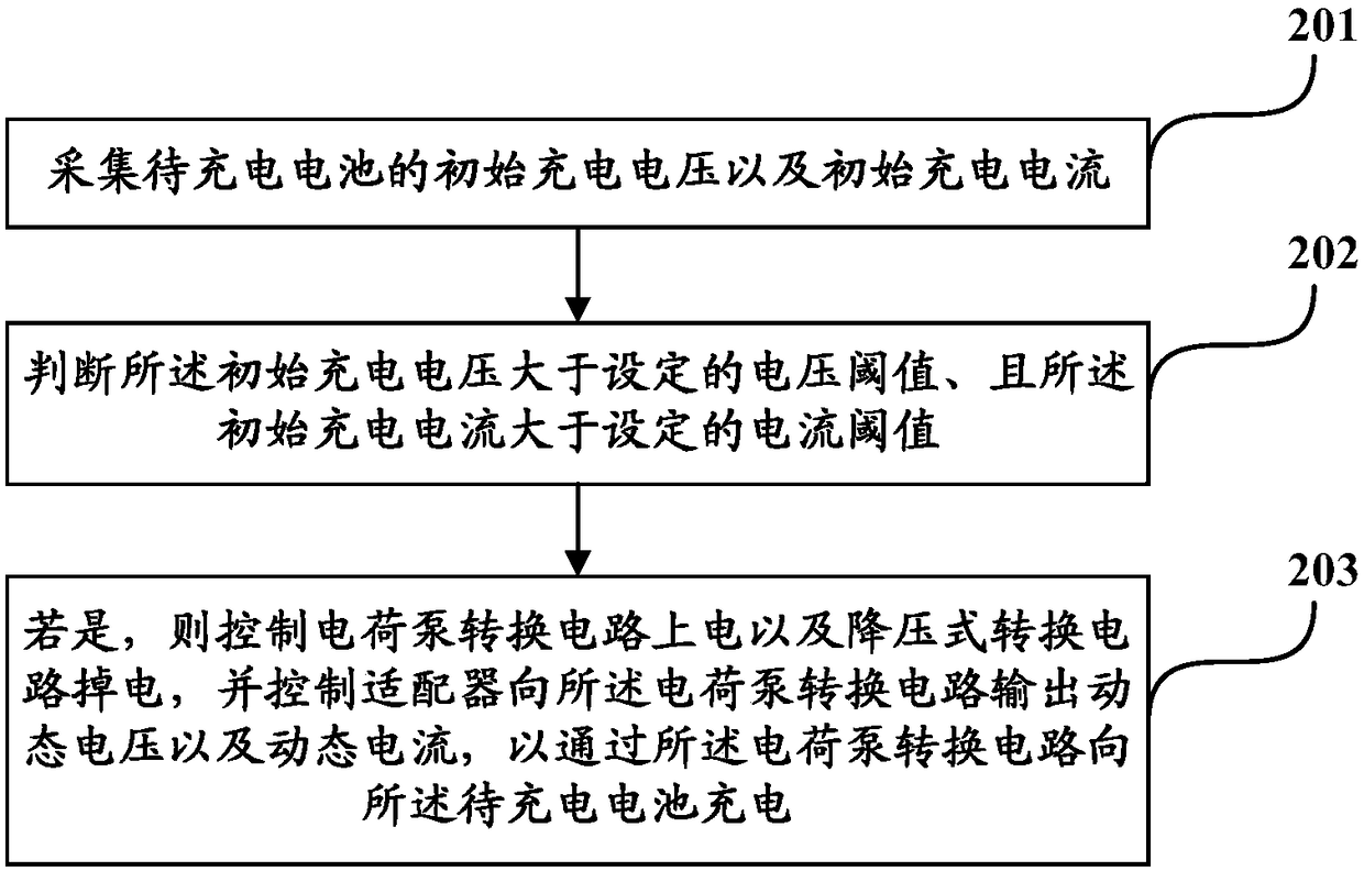
[0026] In order to solve the problems of low step-down conversion efficiency, slow charging speed and serious heat generation in the existing charging control method, Embodiment 1 of the present invention provides a charging control method, such as figure 2 , which is a schematic flow chart of the steps of the charging control method described in Embodiment 1 of the present invention. Specifically, by figure 2 It can be seen that the charging control method may include the following steps:

[0027] Step 201: collecting the initial charging voltage and initial charging current of the battery to be charged;

[0028] Step 202: Judging that the initial charging voltage is greater than a set voltage threshold and the initial charging current is greater than a set current threshold;

[0029] Step 203: If yes, control the power-on of the charge pump conversion circuit and the power-off of the step-down conversion circuit, and control the adapter to output dynamic voltage and dyna...

Embodiment 2

[0118] Based on the same inventive concept as the embodiment of the present invention, Embodiment 2 of the present invention provides a charging control device, such as Figure 8 As shown in , it is a schematic structural diagram of the charging control device described in Embodiment 2 of the present invention. Specifically, by Figure 8 It can be seen that the charging control device may include:

[0119] The collection module 81 can be used to collect the initial charging voltage and initial charging current of the battery to be charged;

[0120] The control module 82 can be used to judge that the initial charging voltage is greater than the set voltage threshold, and the initial charging current is greater than the set current threshold, and if so, control the power-on of the charge pump conversion circuit and the power-off of the step-down conversion circuit , and control the adapter to output a dynamic voltage and a dynamic current to the charge pump conversion circuit,...


PUM


Abstract

The invention discloses a charging control method and device, which can collect the initial charging voltage and initial charging current of a battery to be charged; The current threshold value, then control the power-on of the charge pump conversion circuit and the power-off of the step-down conversion circuit, and control the adapter to output dynamic voltage and dynamic current to the charge pump conversion circuit to pass through the charge pump conversion circuit Charge the battery to be charged. Compared with the prior art, due to the use of a high-efficiency charge pump conversion circuit during high-current charging, the step-down conversion efficiency is effectively improved, the charging speed is accelerated, and the charging time is shortened; and, because the charge pump conversion circuit It does not contain inductive devices that are prone to heat generation, so it can further solve the heating problem of the circuit during charging.

Description

technical field [0001] The present invention relates to the technical field of charging, in particular to a charging control method and device. Background technique [0002] At present, when people charge terminal devices (such as mobile phones, tablet computers, etc.), they usually use a charging system including an adapter and a Buck Switch Charger (Buck) circuit (such as figure 1 As shown, which is a structural schematic diagram of the charging system described in the prior art) to complete the entire charging stage. Specifically, by figure 1 It can be known that the charging system described in the prior art may include an adapter 11 , a step-down conversion circuit 12 and a battery 13 to be charged. Wherein, the charging phase may include a trickle phase, a pre-charging phase, a CC (Constant Current, constant current) phase, and a CV (Constant Voltage, constant voltage) phase. [0003] Specifically, in the prior art, the adapter can only output a fixed voltage (such ...

Claims


Application Information

Patent Timeline
Patent Type & Authority Patents(China)
IPC IPC(8): H02J7/00H01M10/44
CPCH01M10/44H02J7/02H02J7/00714H02J7/007182H02J2207/20Y02E60/10Y02B40/00
Inventor 陈林锋黄昌松
Owner MEIZU TECH CO LTD
Why Eureka
Try Eureka