
An ultrasonic anti-collision radar system and its obstacle positioning method

An anti-collision radar and obstacle technology, applied in radio wave measurement system, sound wave reradiation, instruments, etc., can solve the difficulty of increasing the detection of obstacles in the blind area, the ground is misjudged as an obstacle, and it is easy to cover the ground and be reflected And other issues

Active Publication Date: 2019-11-29
GREAT WALL MOTOR CO LTD
View PDF11 Cites 0 Cited by
  • Summary
  • Abstract
  • Description
  • Claims
  • Application Information

AI Technical Summary

Problems solved by technology

Moreover, in order to make the ultrasonic coverage of the ultrasonic sensor as close as possible to the rear bumper, the outer surface must face the ground, which will make the ultrasonic waves emitted by the ultrasonic sensor easily cover the ground and be reflected, and the ultrasonic anti-collision radar device will be reflected back by the ground. After the ultrasonic wave, the ground will be misjudged as an obstacle; in addition, because the obstacle may be in a static state or in a moving state when parking, this increases the difficulty of detecting obstacles in the blind area; therefore, it is urgent to propose a An ultrasonic anti-collision radar system can detect obstacles in the blind area according to the type of obstacles when detecting obstacles in the blind area, and can also avoid misjudging the ground as being in the blind area by adjusting the installation angle and installation height of the ultrasonic sensor the obstacle problem

Method used


Image

  • An ultrasonic anti-collision radar system and its obstacle positioning method
  • An ultrasonic anti-collision radar system and its obstacle positioning method
  • An ultrasonic anti-collision radar system and its obstacle positioning method

Examples


Embodiment Construction

[0083] It should be noted that, in the case of no conflict, the embodiments of the present invention and the features in the embodiments can be combined with each other.

[0084] The present invention will be described in detail below with reference to the accompanying drawings and examples.

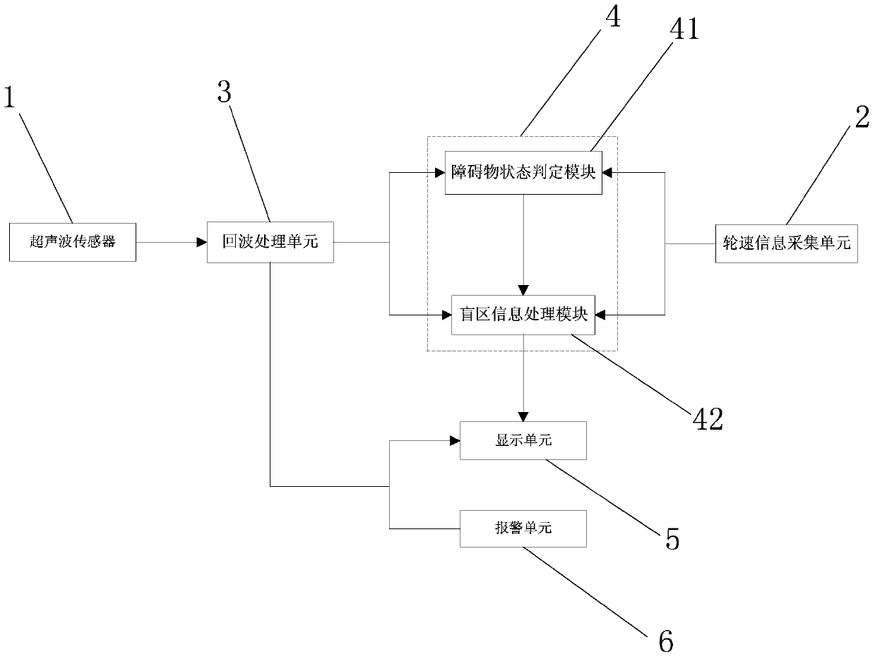
[0085] see figure 1 , an embodiment of the present invention provides an ultrasonic anti-collision radar system, including an ultrasonic sensor 1, an echo processing unit 3, an analog information processing unit 4, and a display unit 5; wherein,

[0086] The analog information processing unit 4 includes an obstacle state judging module 41 and a blind spot information processing module 42 connected to the obstacle state judging module 41;

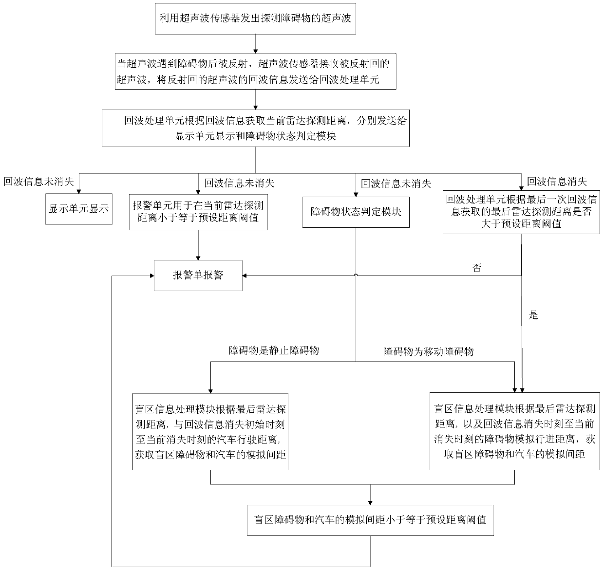
[0087] The ultrasonic sensor 1 is connected to the echo processing unit 3, and is used to send ultrasonic waves for detecting obstacles, receive ultrasonic waves reflected by obstacles, and send echo information of the reflected ultrasonic waves to th...


PUM


Abstract

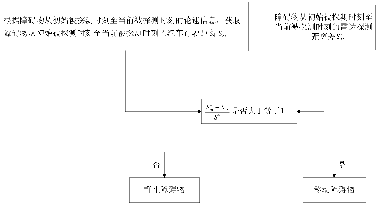
The invention provides an ultrasonic crash-proof radar system and a barrier positioning method thereof, and relates to the field of automobile safety, for realizing the purposes of detecting blind area barriers according to barrier types and preventing wrongly determining the ground as a barrier. The system comprises an ultrasonic sensor, an echo processing unit, a barrier state determining module and a blind area information processing module. During work, the echo processing unit sends processed information to a display unit, the barrier state determining module identifies a barrier type, when echo information is not received and an obtained final radar detection distance is greater than a preset distance threshold, according to the barrier type determined by the barrier state determining module, the blind area information processing module obtains data used for display in the display unit by use of rotating speed information and the final radar detection distance. The system can perform the detection on the blind area barriers according to the barrier types and avoids the problem of determining the ground as the barrier. The ultrasonic crash-proof radar system is applied to the field of automobile safety.

Description

technical field [0001] The invention relates to the technical field of automobile safety, in particular to an ultrasonic anti-collision radar system and an obstacle positioning method thereof. Background technique [0002] The ultrasonic anti-collision radar device is a safety device installed on a car to help the driver complete parking smoothly. It has high adaptability to the environment and is not affected by environmental factors, so it is widely welcomed by people. At present, the common ultrasonic anti-collision radar device mainly relies on the ultrasonic sensor installed on the rear bumper of the car to emit ultrasonic waves and receive the ultrasonic waves reflected by obstacles. After the reflected ultrasonic waves are processed, the distance between the obstacles and the car can be obtained. , and finally displayed on the display unit. However, the ultrasonic sensor has strict requirements on the installation height and installation angle, and it is easy to have...

Claims


Application Information

Patent Timeline
Patent Type & Authority Patents(China)
IPC IPC(8): G01S15/93
CPCG01S15/931G01S2015/932
Inventor 魏宏高波崔子国高通胡博范志超朱鹏吉尹俊学杜丹丹
Owner GREAT WALL MOTOR CO LTD
Learn More