
Take-up lever locking mechanism and embroidery machine

A technology of locking mechanism and thread take-up lever, which is applied in the field of embroidery machines and can solve problems such as no practical significance

Active Publication Date: 2017-05-24
ZHEJIANG XINSHENG SEWING EQUIP
View PDF11 Cites 2 Cited by
  • Summary
  • Abstract
  • Description
  • Claims
  • Application Information

AI Technical Summary

Problems solved by technology

[0003] Since the rotation of the main shaft does not cause the movement of the needle bar, the movement of the thread take-up lever is an empty stroke, which has no practical significance

Method used


Image

  • Take-up lever locking mechanism and embroidery machine
  • Take-up lever locking mechanism and embroidery machine

Examples


Embodiment 1

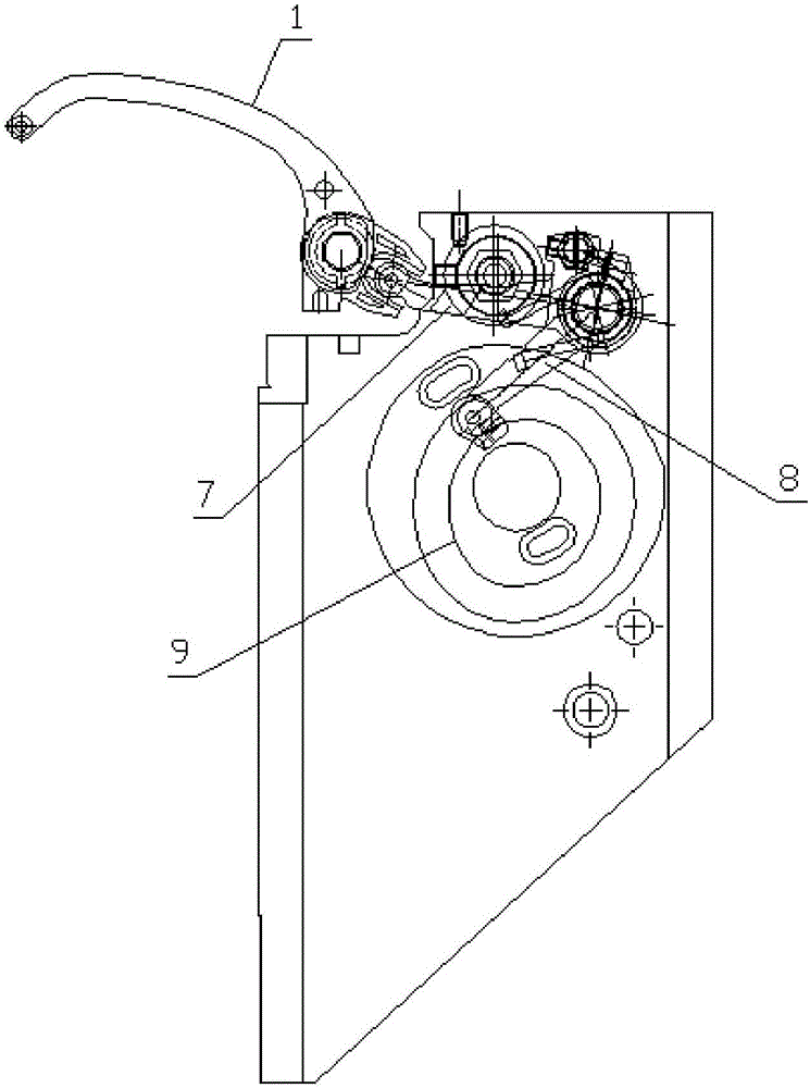
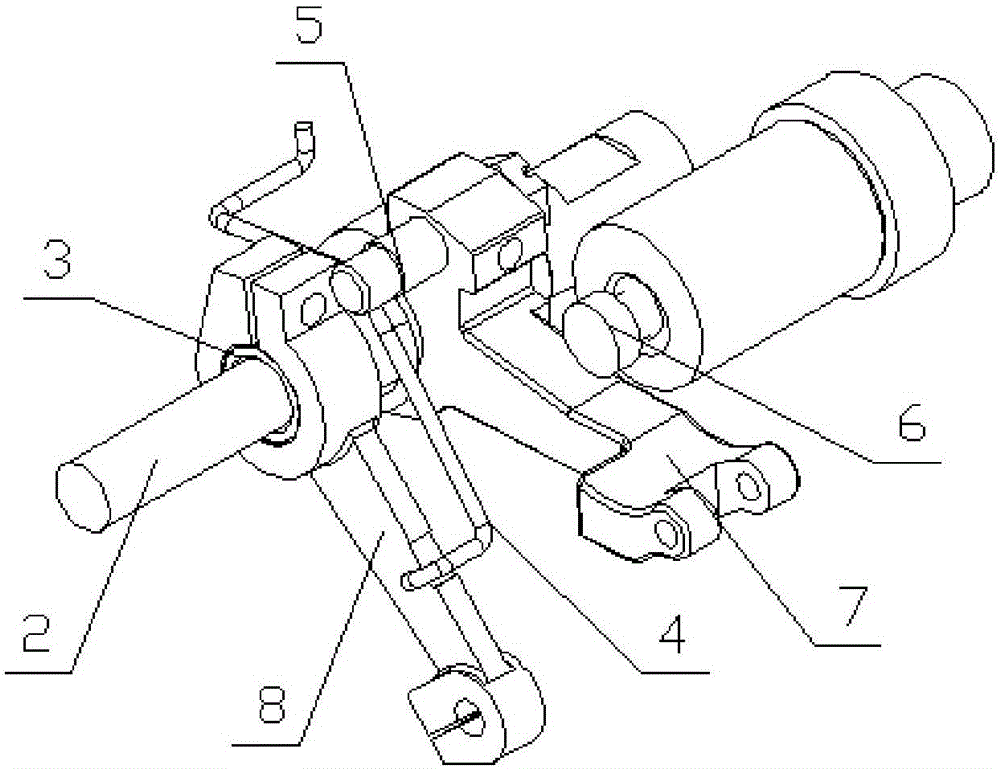
[0015] Example 1, such as figure 1 with figure 2 As shown, a thread take-up lever locking mechanism includes a main shaft mounted on a machine head housing, a thread take-up cam 9, a thread take-up A7, a thread take-up B8, and a thread take-up lever 1. The thread take-up cam 9 is mounted on the main shaft The thread take-up B8 is driven by the thread take-up cam 9. The end of the thread take-up B8 is provided with a roller, and the roller is embedded in the cam groove of the thread take-up cam 9, and the thread take-up A7 is driven by the thread take-up cam 9. The thread B8 drives and drives the thread take-up lever 1 to move.

[0016] Among them, the thread take-up A7 and the thread take-up B8 are not locked, and the thread take-up A7 and the thread take-up B8 are rotated and nested on the thread take-up sleeve 3. Therefore, the thread take-up A7 and the thread take-up B8 can be combined with the thread take-up sleeve 3. Turn each other. The thread take-up sleeve 3 is install...

Embodiment 2

[0019] Embodiment 2, an embroidery machine, is equipped with the thread take-up lever locking mechanism described above.

[0020] With the traditional structure, when the color is changed, the needle bar does not lower the needle, and the thread take-up lever makes an empty stroke, which will cause an empty pull of the upper thread. Because the upper thread is not consumed in this round of the thread take-up lever, the upper thread is lowered. The tension of the needle thread is not tight enough, which affects the quality of high-end embroidery. When a certain needle position is broken and the thread needs to be mended, the existing machine uses the needle bar of the mending needle position to move, while the needle bars of other needle positions are stationary, but the thread take-up levers of all needle positions are moving. This causes the empty stroke of the thread take-up levers of other needle positions, which affects the quality of the next needle embroidery of all other n...


PUM


Abstract

The invention discloses a take-up lever locking mechanism and an embroidery machine. The take-up lever locking mechanism comprises a main shaft, a take-up cam, a taken-up thread A, a taken-up thread B and a take-up lever, wherein the take-up cam is mounted on the main shaft and rotates with the main shaft, the taken-up thread B is driven by the take-up cam, the taken-up thread A is driven by the taken-up thread B and enables the take-up lever to act, the taken-up thread A and the taken-up thread B are rotationally nested on a taken-up thread sleeve, the taken-up thread sleeve is mounted on a taken-up pin, a torsional spring is mounted on the taken-up thread sleeve, the two ends of the torsional spring respectively button up the taken-up thread A and the taken-up thread B, torsion of the torsional spring enables the taken-up thread A and the taken-up thread B to rotate towards the direction that an angle increases, and the taken-up thread A is provided with a take-up stop pin which enables the taken-up thread A to rotate downwards when the taken-up thread B rotates downwards. The take-up lever locking mechanism and the embroidery machine guarantee movement law of the taken-up thread A and the taken-up thread B in a normal embroidery state, and idle stroke in movement of the take-up lever is avoided.

Description

Technical field [0001] The invention relates to an embroidery machine, in particular to a thread take-up lever locking mechanism. Background technique [0002] Such as figure 1 As shown, the end of the thread take-up B8 has a roller, which is embedded in the cam groove of the thread take-up cam 9. The thread take-up cam 9 is fixedly connected to the main shaft and rotates with the main shaft. When the embroidery machine changes colors, the main shaft continues to rotate, and the thread take-up cam 9 also continues to rotate to drive the thread take-up B8 to make a reciprocating swing. In the traditional thread take-up mechanism, the thread take-up A7 and the thread take-up B8 are locked, and the mutual angle is a fixed value. Therefore, the movement of the thread take-up B8 will inevitably drive the movement of the thread take-up A7, so that the thread take-up lever 1 will reciprocate. swing. [0003] Since this spindle rotation does not cause the needle bar to move, the thread t...

Claims


Application Information

Patent Timeline
Patent Type & Authority Applications(China)
IPC IPC(8): D05C11/00
CPCD05C11/00D05D2209/08
Inventor 王海江
Owner ZHEJIANG XINSHENG SEWING EQUIP
Learn More