Revolution speed detection device

A detection device and technology of rotation speed, which is applied in the direction of measurement device, linear/angular velocity measurement, speed/acceleration/impact measurement, etc., and can solve the problem that the rotation detection wheel affects the detection results and other problems

Active Publication Date: 2017-06-09
重庆顺多利机车有限责任公司
View PDF8 Cites 1 Cited by
  • Summary
  • Abstract
  • Description
  • Claims
  • Application Information

AI Technical Summary

Problems solved by technology

[0005] The purpose of the present invention is a rotation speed detection device to solve the techn

Method used


Image

  • Revolution speed detection device
  • Revolution speed detection device
  • Revolution speed detection device

Examples


Embodiment Construction

[0020] The present invention will be described in further detail below by means of specific embodiments:

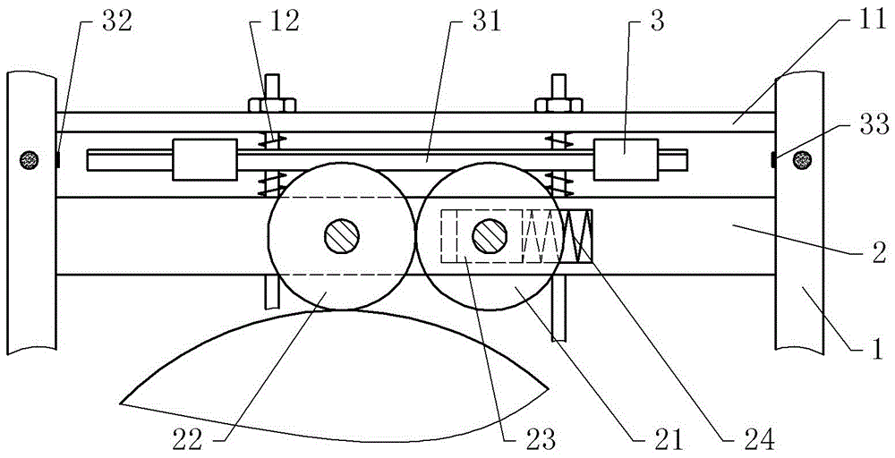
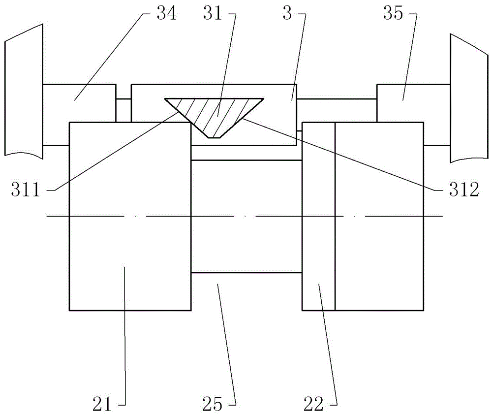
[0021] The reference numerals in the drawings of the description include: bracket 1, adjusting pressure plate 11, first spring 12, mounting seat 2, first roller 21, second roller 22, slider 23, second spring 24, annular groove 25, Slide seat 3 , slide bar 31 , first control switch 32 , second control switch 33 , second cylinder 34 , first cylinder 35 , first contact surface 311 , second contact surface 312 .

[0022] The embodiment is basically as figure 1 , figure 2 , image 3 Shown:

[0023] The rotation speed detecting device of the present embodiment includes a bracket 1, a rolling part, a sliding part, a counting part and a display screen; the rolling part includes a mounting seat 2, a slider 23, a first roller 21 and a second roller 22; the sliding part includes a sliding seat 3 and a sliding bar 31; the counting part includes a distance sensor and an encoder; ...


PUM


Abstract

The invention discloses a revolution speed detection device, and relates to the machining apparatus; the revolution speed detection device mainly comprises a support, a rolling portion, a slide portion and a counting portion; the rolling portion comprises a mount seat, a slide block, a first roller and a second roller; the slide portion comprises a slide seat and a slide bar; the mount seat and the slide seat are connected on the support in a slide manner; the slide block is connected on the mount seat in a slide manner; the first roller is connected on the mount seat in a rotary manner; the second roller is connected with the slide block in a rotary manner; a first spring is arranged between the support and the mount seat; a second spring is arranged between the slide block and the mount seat; the slide bar is arranged above the first and second rollers; two ends of the slide bar are respectively provided with a first control switch and a second control switch; the slide bar impacts the first control switch and tightly attaches to the first roller; the slide bar impacts the second control switch and tightly attaches to the second roller; the slide bar can measure the linear speed of the first and second roller edges, and the measuring result is not affected by the first and second roller grinding.

Description

technical field [0001] The invention relates to the field of mechanical processing, in particular to a rotation speed detection device. Background technique [0002] At present, the common method for detecting the angle of the slewing mechanism of heavy machinery is to install the encoder on the shaft end of the slewing detection gear through a coupling, and the slewing detection gear rotates synchronously, and the slewing detection gear meshes with the slewing steel structure drive pinion, and The rotary steel structure drive pinion gear meshes with the external teeth of the large rotary bearing to detect the rotary angle. The disadvantages of this scheme: (1) The transmission between the gears will wear out after long-term use, and the backlash of the teeth will increase, which will affect the detection accuracy; (2) There is no automatic compensation function after wear and tear, which can only be compensated by replacing the gears; (3) ) The processing and manufacturing...

Claims


Application Information

Patent Timeline
IPC IPC(8): G01P3/00G01B21/22
CPCG01B21/22G01P3/00
Inventor 王文革
Owner 重庆顺多利机车有限责任公司
Why Eureka
Try Eureka