A compressed air energy storage system with non-throttling humidification and enthalpy increase

A compressed air energy storage, non-throttling technology, applied in steam engine installations, engine components, machines/engines, etc. In order to reduce the volume of the turbine, improve the working capacity, and reduce the cost

Active Publication Date: 2018-08-03
NORTH CHINA ELECTRIC POWER UNIV (BAODING)
View PDF4 Cites 0 Cited by
  • Summary
  • Abstract
  • Description
  • Claims
  • Application Information

AI Technical Summary

Problems solved by technology

The superposition of the two factors will eventually lead to a significant decrease in the temperature of the compressed air at the turbine inlet, a large throttling loss, and a significant decrease in the working capacity of the working medium.
And the lowering of the inlet temperature of the turbine will reduce the turbine power. In order to ensure the stability of the turbine power, the flow rate of the working medium must be increased accordingly, and the opening of the throttling and pressure-reducing valve must be opened to increase the turbine inlet pressure. , which will exacerbate the instability of turbine inlet working fluid parameters, and ultimately lead to instability of turbine operating conditions

Method used


Image

  • A compressed air energy storage system with non-throttling humidification and enthalpy increase
  • A compressed air energy storage system with non-throttling humidification and enthalpy increase

Examples


Embodiment 1

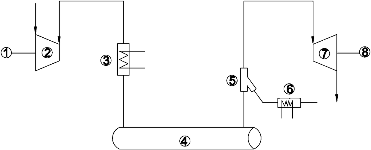
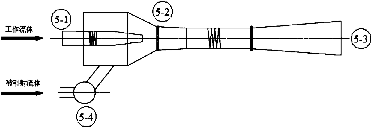
[0030] like Figure 1-2 As shown, this embodiment takes a compressed air energy storage power station as an example, and makes a detailed description of the specific structure and working principle of the non-throttling humidification and enthalpy-increasing compressed air energy storage system of the present invention.

[0031] like figure 1 As shown, this embodiment provides a compressed air energy storage system with non-throttling humidification and enthalpy increase, including a motor 1, a compressor 2, an air heat exchanger 3, an air storage chamber 4, a feed water heater 6, an ejector Flash evaporator 5, turbine 7 and generator 8; the outlet of the compressor 2 is connected to the inlet of the air heat exchanger 3 through a pipeline, and the outlet of the air heat exchanger 3 is connected to the inlet of the air storage chamber 4 through a pipe The air release port of the gas storage chamber 4 is connected with the working nozzle 5-1 of the ejector flash evaporator 5 t...


PUM


Abstract

The invention discloses a non-throttling humidifying and enthalpy-increasing compressed air energy storage system. The non-throttling humidifying and enthalpy-increasing compressed air energy storage system comprises an air compressor, an air heat exchanger, an air storage chamber, a feed water heater and an injection flash evaporator. An outlet of the air compressor is connected with an inlet of the air heat exchanger through a pipeline. An outlet of the air heat exchanger is connected with an inlet of the air storage chamber through a pipeline. A relief port of the air storage chamber is connected with a working nozzle of the injection flash evaporator through a pipeline. An injection flash evaporation pipe of the injection flash evaporator is connected with a water side outlet of the feed water heater through a pipeline. A water side inlet of the feed water heater is connected with a water source. An outlet of the injection flash evaporator is connected with a turbine. The non-throttling humidifying and enthalpy-increasing compressed air energy storage system is based on the injection and flash evaporation principle, the pressure of mixed working media is decreased by mixing compressed air with high-temperature water or water vapor, the power capacity of the working media of unit volume is obviously higher than that of compressed air under traditional identical temperature and pressure parameter conditions, and the output power of the compressed air energy storage system can be remarkably improved; and in addition, a heat storage device does not need to be arranged, and the cost performance is high.

Description

technical field [0001] The invention relates to the technical field of thermal power generation, in particular to a compressed air energy storage system for non-throttling humidification and enthalpy increase. Background technique [0002] At present, the demand for electricity continues to grow, and the share of renewable energy power generation is increasing year by year. Due to the inherent intermittent shortcomings of renewable energy and the increasing difference between peak and valley power consumption on the user side, these problems make the power grid peak shaving problem It is very prominent that the development of energy storage technology can effectively stabilize the peak and valley fluctuations of power grid load. [0003] Compressed air energy storage power station has the advantages of high energy storage efficiency and low cost per unit energy storage power, and is one of the technical means suitable for large-scale electric energy storage. The basic worki...

Claims


Application Information

Patent Timeline
Patent Type & Authority Patents(China)
IPC IPC(8): F01K27/00F01D17/00F01D15/10
CPCF01D15/10F01D17/00F01K27/00
Inventor 冉鹏庄续增王亚瑟高建强李政刘培
Owner NORTH CHINA ELECTRIC POWER UNIV (BAODING)
Why Eureka
Try Eureka