Hyper spectral imaging device and method based on birefringence polarization interferometry

A hyperspectral imaging and imaging method technology, applied in the field of hyperspectral imaging devices, to achieve low complexity, reduce manufacturing costs, and increase stability

Inactive Publication Date: 2017-06-20
南京衍射光电科技有限公司
View PDF6 Cites 5 Cited by
  • Summary
  • Abstract
  • Description
  • Claims
  • Application Information

AI Technical Summary

Problems solved by technology

[0005] The problem to be solved by the present invention is: in order to solve the complexity and stability problems of the hyperspectral imaging device, a hyperspectral imaging device and method for combining a single Wollaston prism and a pyramidal reflector into a transverse shearing beam splitter are proposed

Method used


Image

  • Hyper spectral imaging device and method based on birefringence polarization interferometry
  • Hyper spectral imaging device and method based on birefringence polarization interferometry
  • Hyper spectral imaging device and method based on birefringence polarization interferometry

Examples


Embodiment 1

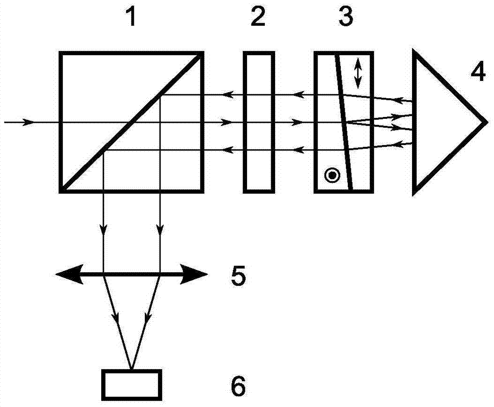
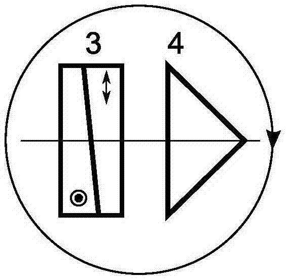
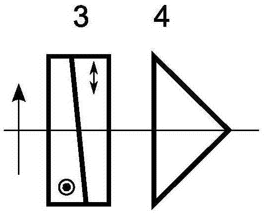
[0064] This embodiment is based on figure 1 The hyperspectral imaging device shown includes a polarizing beam splitter 1, a half-wave plate 2, a Wollaston prism 3, and a pyramidal reflector 4 placed in sequence along the incident light direction, and an imaging objective lens 5 and a detection lens arranged in sequence on the outgoing light path. Device 6, polarizing beam splitter 1, half-wave plate 2, Wollaston prism 3 and pyramid reflector 4 have a common central axis, which is called the first optical axis, and the imaging objective lens 5 and detector 6 have a common central axis, which is called the second light axis; the transmission direction of the polarizing beam splitter 1 is the same as the crystal optical axis direction of one of the wedge plates of the Wollaston prism 3, and is perpendicular to the first optical axis and parallel to the second optical axis; the fast axis of the half-wave plate 2 is parallel to the second optical axis; The included angle of the vib...

Embodiment 2

[0075] This embodiment is based on Figure 6 In the hyperspectral imaging device shown, on the basis of Embodiment 1, a first phase retarder 7 and a second phase retarder 8 are sequentially placed in front of the polarization beam splitter 1 along the direction of incident light; the first phase retarder 7 The fast axes of the second phase retarder 8 and the second phase retarder 8 are both perpendicular to the first optical axis; the placement requirements of other optical components are the same as those of Embodiment 1.

[0076] The first phase retarder 7 and the second phase retarder 8 can be birefringent crystals at the same time, or liquid crystal variable phase retarders at the same time.

[0077] When the first phase retarder 7 and the second phase retarder 8 are birefringent crystals, the crystal thickness ratio of the two is 1:2, the angle between the fast axes of the two is 45°, and the fast axis of the first phase retarder 7 The axis is parallel to the vibration t...

Embodiment 3

[0081] This embodiment is based on Figure 7 In the hyperspectral imaging device shown, on the basis of Example 1, a first ferroelectric liquid crystal 9, a first phase retarder 10, and a second ferroelectric liquid crystal 11 are sequentially placed in front of the polarizing beam splitter 1 along the direction of incident light. and the second phase retarder 12, the fast axes of the first ferroelectric liquid crystal 9, the first phase retarder 10, the second ferroelectric liquid crystal 11 and the second phase retarder 12 are all perpendicular to the first optical axis; The placement requirements are the same as in Example 1.

[0082] The optical path retardation of the first ferroelectric liquid crystal 9 at a wavelength of 510nm is 298nm, and the included angle between the fast axis and the vibration transmission direction of the polarizing beam splitter 1 is 90°; the optical path of the first phase retarder 10 at a wavelength of 465nm The retardation is 416nm, and the i...


PUM


Abstract

The invention relates to a hyper spectral imaging device and method based on birefringence polarization interferometry. The hyper spectral imaging device comprises a polarization beam splitter, a half-wave plate, a Wollaston prism, a pyramid reflector, an imaging objective and a detector. Incident light from a target produces interference on the detector, by means of a built-in interferometric scanning mode, the detector obtains the interferometric image information of the target, and finally spectrum information of the target is obtained through Fourier transform spectrum reconstruction. According to the invention, one Wollaston prism and the pyramid reflector are combined to form a transverse shearing beam splitter for the first time, the complex rate and the manufacture cost of a hyper spectral imager are reduced, and the system stability and the spectrum reconstruction precision are improved. The hyper spectral imaging device and method provide an effective technological approach for a hyper spectral imager which is low in complex rate and high in stability, and is light, small and multifunctional.

Description

technical field [0001] The invention belongs to the technical field of spectral imaging, and relates to a hyperspectral imaging device and method based on the principle of birefringence polarization interference, which can be used for imaging spectral analysis of objects, spectral analysis of free-space light beams or optical fiber-introduced light beams, and can also be used in combination with polarization modulation technology Spectral and polarization characteristics analysis of the target to be measured. Background technique [0002] Hyperspectral imaging technology combines imaging technology with spectral technology. While obtaining two-dimensional spatial information of the target to be measured, it also obtains fine spectral information. The core significance of this technology lies in the subdivision imaging of visible light and infrared radiation. , to provide an effective judgment method for the analysis of the characteristics of substances, and has great potenti...

Claims


Application Information

Patent Timeline
Patent Type & Authority Applications(China)
IPC IPC(8): G01J3/447G01N21/25G01J3/28
CPCG01J3/447G01J3/2823G01N21/25
Inventor 李建欣
Owner 南京衍射光电科技有限公司
Why Eureka
Try Eureka