
Coupler assembly and straddle-type railway train with same

A component and coupler technology, which is applied to railway car body components, railway vehicle coupling accessories, transportation and packaging, etc., can solve problems such as damage, non-interference, and aesthetic impact, and achieve low requirements for opening and closing devices. The process is simple and convenient, and the appearance is beautiful

Active Publication Date: 2017-07-28
BYD CO LTD
View PDF8 Cites 21 Cited by
  • Summary
  • Abstract
  • Description
  • Claims
  • Application Information

AI Technical Summary

Problems solved by technology

[0003] Furthermore, for the low-floor rail vehicles with low running speed, due to the comprehensive consideration of the aesthetics of the car body, the front of the car does not need to be streamlined, and the width of the front of the car is relatively large. The fronts do not interfere with each other, and the longitudinal gap between the two connected vehicles should not be less than a certain critical value, that is, the coupling surface of the coupler should protrude a certain distance outside the front. If the existing coupler is used, the end of the coupler It is exposed outside for a long time, which affects the appearance. If the opening and closing device is used to cover it, the requirements for the opening and closing device are very high. In addition, because the track has a curved section and a ramp, it is often impossible to ensure that the rail vehicle passes through. The levelness of the coupler, the coupler is easy to be damaged due to uneven force

Method used


Image

  • Coupler assembly and straddle-type railway train with same
  • Coupler assembly and straddle-type railway train with same
  • Coupler assembly and straddle-type railway train with same

Examples


Embodiment Construction

[0070] The embodiments of the present invention are described in detail below, and examples of the embodiments are shown in the accompanying drawings. The embodiments described below with reference to the accompanying drawings are exemplary, and are intended to explain the present invention, but should not be construed as limiting the present invention.

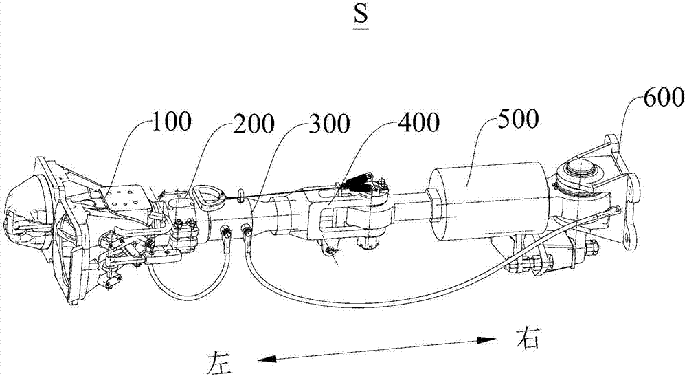
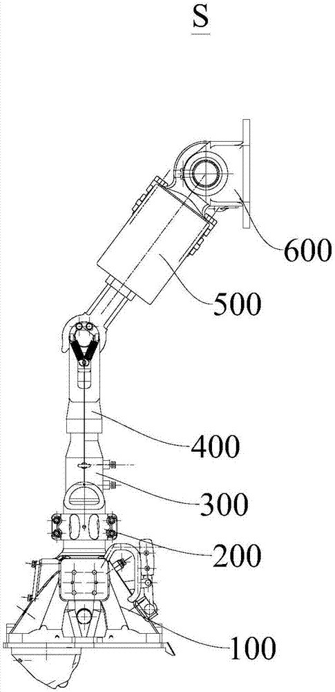
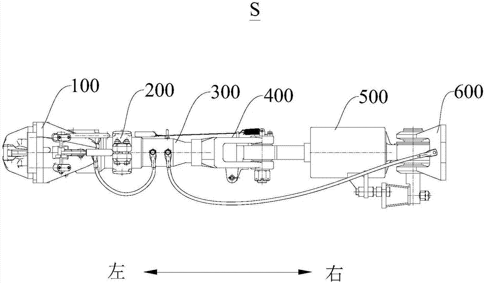
[0071] The following first combines Figure 1 to Figure 13 The coupler assembly S according to the embodiment of the first aspect of the present invention is specifically described.

[0072] The coupler assembly S according to the embodiment of the present invention includes a mounting seat 600, a buffer mechanism 500, a folding mechanism 400 and a hook head 100.

[0073] Specifically, the mounting base 600 is suitable for mounting on a vehicle, one end of the buffer mechanism 500 is movably connected to the mounting base 600, the other end of the buffer mechanism 500 is provided with a pull rod 513, and the pull rod 513 is provide...


PUM


Abstract

The invention discloses a coupler assembly and a straddle-type railway train with the same. The coupler assembly comprises a mounting seat, a buffer mechanism, a folding mechanism and a coupler head; one end of the buffer mechanism is movably connected with the mounting seat, and the other end of the buffer mechanism is provided with a pulling rod; a limiting part is arranged on the pulling rod; one end of the folding mechanism is movably connected with the pulling rod; a locking piece is arranged on the folding mechanism and movably matched with the limiting part to lock or loosen the pulling rod; when the limiting part is locked by the locking piece, the pulling rod is fixed in the stretching position, and when the limiting part is loosened by the locking piece, the pulling rod can move between the folding position and the stretching position; and one end of the coupler head is connected with the other end of the folding mechanism. According to the coupler assembly of the embodiment of the invention, locking or loosening of the pulling rod is realized through the matching effect between the locking piece and the limiting part of the pulling rod, coupling between adjacent train bodies with large train head widths is further realized, the operation process is easy and convenient, and the requirement for an opening and closing device is low.

Description

Technical field [0001] The present invention relates to the technical field of rail vehicle manufacturing, in particular to a coupler assembly and a straddle-type rail train having the same. Background technique [0002] The coupler in the related art does not have a folding function. This type of coupler is suitable for high-speed trains with a streamlined front (to avoid the aerodynamic disadvantage of the front). Because the train usually has an opening and closing device at the front, it is not connected. In the hanging state, the opening and closing device is closed to hide the coupler in the car body. Only when it is connected, the opening and closing device is opened, and the coupling end of the coupler is exposed outside the car body so that the coupler can be connected. And because the car body is made into a streamlined size and smaller, when the two cars are connected, the length of the coupler exposed to the outside of the car body is the smallest, which can also ensu...

Claims


Application Information

Patent Timeline
Patent Type & Authority Applications(China)
IPC IPC(8): B61G7/10B61G9/08B61G9/20
CPCB61G7/10B61G9/08B61G9/20B61G9/06B61G9/04
Inventor 肖志鸿李道林谭志成
Owner BYD CO LTD
Learn More